Workshop manual 510 16 77-26
Contents Workshop manual Jonsered CS 2240 and CS 2240S Contents Index........................................................................ 4 Introduction and safety instructions.................... 6 Technical data....................................................... 10 Service tools......................................................... 12 Service data.......................................................... 14 Safety equipment..................................................
Index B Index Symbols in the Workshop Manual 9 Symbols on the saw 9 Structure 7 Target group 7 Tools 7 Bar bolt 52 Replacing the bar bolt 52 C Carburettor 33 Assemble on the saw 40 Assembly 38 Carburettor adjustment 41 Cleaning and inspection 37 Design 33 Dismantling 35 Function 34 Pressure testing the carburettor 39 Centrifugal clutch 30 Centrifugal clutch - refitting 31 Centrifugal clutch - removal 30 Inspection and cleaning 30 Chain brake 17 Chaine brake - reassembly 18 Cleaning and inspection 17 Di
Index Trouble shooting 54 Trouble-shooting methods 55 V Vibration damping system 43 Assembly 43 Cleaning and inspection 43 Dismantling 43 English – 5
Introduction and safety instructions 2 Introduction and safety instructions Contents 2.1 2.2 2.3 2.4 2.5 2.6 2.7 2.8 2.9 2.10 2.11 General . ..........................................................................................................................7 Safety ..............................................................................................................................7 Target group .................................................................................................
Introduction and safety instructions 2 Introduction and safety instructions 2.1 General 2.6 Structure This Workshop Manual describes in detail how the chain saw is to be fault traced, repaired and tested. A description of different safety measures that should be taken during repair work is also given. This Workshop Manual can be used in two different ways: • 2.2 Safety For the repair of a particular system on the chain saw. • Dismantling and assembly of the entire chain saw.
Introduction and safety instructions 2.8 General instructions 2.9 Special instructions The workshop where chain saw repairs are to be done must be equipped with safety equipment as set out in local provisions. The fuel that is used in a chainsaw poses the following hazards: No one may repair the chain saw unless they have read and understood the content of this Workshop Manual. In this workshop manual the following boxes indicate where caution should be taken.
Introduction and safety instructions 2.10 Symbols on the saw 2.11 Symbols in the Workshop Manual The symbols below are embedded on the chain saw.
Technical data 3 Technical data CS 2240/S: Displacement cm3/cubic inches Cylinder bore Ø mm/Ø inches Stroke mm/inches Max power/speed kW/hp/rpm 40,9 / 2,49 41 / 1,51 31 / 1,22 1,8 / 2,4 / 9 000 Spark plug gap Ignition system mm/inches CS 2240/S: 0,5 / 0,02 Effective cutting length cm/inches CS 2240/S: 33-46 / 13-18 10 – English Walbro MBU-16 Air gap mm/inches Carburettor type 0,3 / 0,012 Zama EL41AC1T Chain speed at max power – revs m/s - r/min Chain pitch mm/inches Drive link mm/
Technical data rpm Idling speed rpm Engagement speed rpm Spark plug CS 2240/S: 2 900 3 800 NGK BPMR 7A Champion RCJ 7Y GAS Fuel tank capacity Litres/US pints CS 2240/S: 0,37 / 0,78 Weight without bar and chain kg / lbs CS 2240/S: 4,4 / 9,7 OIL Oil pump capacity at 8,500 rpm, ml/min Oil tank capacity Litres/US pints Automatic oil pump 9 0,25 / 0,53 Yes Weight with bar and chain kg / lbs 5,7 / 12,6 English – 11
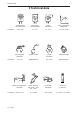
Special tools 4 Special tools 2 1 4 M5 5 3 7 6 M5 M6 8 9 10 11 12 – English
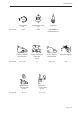
Special tools 12 13a 15 14 13b 16b 16c 17 16a 18 Item 1 2 3 Description Clutch tool Piston stop Fuel filter hook Used for Centrifugal clutch Locking the crankshaft Withdrawing the fuel filter Order no.
Service data 5 Service data 14 – English
Service data English – 15
Safety equipment 6 Safety equipment Contents 6.1 6.2 6.3 6.4 6.5 6.6 6.7 6.8 6.9 6.10 Dismantling the chain brake ............................................................................................17 Chain brake - reassembly ...............................................................................................18 Silencer - removal ...........................................................................................................19 Silencer - refitting ............................
Safety equipment 6 Safety equipment 6.1 Dismantling the chain brake 1 Release the brake by moving the front hand guard backward. Loosen the bar nut and remove the clutch cover, chain and bar (see figure 1). Fig 1 2 Carefully tighten the clutch housing in a vice. Release the brake by using the saw's front hand guard (A) as a tool. Mesh with the brake and tighten anti-clockwise until the brake is activated.
Safety equipment 6.2 Chain brake – reassembly 1 Bolt the elbow joint to the brake band (see figure 5) and tighten to a torque of 1–1.5 Nm. Locate the elbow joint and connected brake band in their recesses in the clutch cover. Lubricate the recess for the spring with grease (see figure 6). Secure the circlip (A) (see figure 6). Fig 6 2 Grip the clutch cover in a vice. Compress the spring with special tool 502 50 67-01 and push it down with your thumb (see figure 7).
Safety equipment Operating test: The engine must not be running during the test. Guide bar length 38cm/15" Height 50 cm/20" • Hold the chainsaw over a firm surface. The height of the guide bar above the surface is given in the table above. • Let go of the front handle and let the chainsaw fall towards the surface. • When the guide bar hits the surface the chain brake must engage (see figure 10). Fig 10 6.
Safety equipment 6.5 Chain catcher – replacement If the chain catcher is worn it must be replaced with a new one. 1 Release the brake by pushing the kickback guard backwards. Undo the guide bar bolts and remove the clutch cover, chain and guide bar. 2 Remove the chain catcher and replace it with a new one. Check that the vibration damping spring locates correctly against the crankcase when you bolt the new chain catcher in position. (see figure 12) Fig 12 6.
Safety equipment 6.7 Stop switch – resistance measurement Clean the mating surfaces and check the resistance as follows: Measure the resistance by connecting a multimeter to the ignition coil. NOTE! The switch must be in the “on” (A) position to give the correct reading (see figure 14). The resistance must not be higher than 0.5 Ohm when the switch is in the on position.
Safety equipment 6.9 Throttle lock, throttle trigger and return spring – removal 1 Loosen the throttle actuator rod on the carburettor, the fuel hose and the suction hose to the fuel pump. A 2 Dismantle the tank unit from the engine unit by loosening the screws A (see figure 17) A Fig 17 3 Dismantle the handle insert (B) by loosening the screw C on the handle (see figure 18). Fig 18 4 Press out the throttle control pin (D) with the help of a punch (see figure 19).
Safety equipment Cleaning and inspection • Clean and inspect all parts carefully. If there are any cracks or other defects replace the damaged parts with new ones. Always use original parts. • Check that the spring is not broken and has not lost its tension. 6.10 Throttle lock, throttle trigger and return spring – refitting 1 Lubricate all pins and mating surfaces with a light oil. 2 Fit the throttle control (B) and spring (C) (see figure 22).
Repair instructions 7 Repair instructions Contents 7.1 7.2 7.3 7.4 7.5 7.6 7.7 7.8 7.9 7.10 7.11 7.12 7.13 7.14 7.15 7.16 7.17 7.18 7.19 7.20 7.21 7.22 7.23 7.24 7.25 7.26 7.27 7.28 7.29 Starter assembly - removal .............................................................................................25 Changing a broken or worn starter cord ..........................................................................26 Tensioning the recoil spring .......................................................
Repair instructions 7 Repair instructions 7.1 Starter assembly – removal 1 Undo the four bolts that fasten the starter assembly to the crankcase and lift off the starter assembly. (see figure 1) Fig 1 2 Pull out about 30 cm of the cord and fasten it in the notch in the pulley rim. Release the tension in the return spring by letting the pulley wind backwards slowly. (see figure 2) WARNING! If the recoil spring is still under tension when the pulley is removed it can fly out and cause injury.
Repair instructions 7.2 Changing a broken or worn starter cord When the starter cord is worn and must be replaced, the tension on the return spring must be released. 1 Pull the cord out about 30 cm and lift it into the notch on the outside of the starter pulley. Release the tension on the return spring by allowing the starter pulley to rotate slowly backwards (see figure 2). WARNING! If the spring tension is activated on the starter pulley, the spring can fly out and cause personal injury.
Repair instructions 7.4 Replacing a worn recoil spring WARNING! Make sure the recoil spring does not fly out and cause injury. Wear eye protection.. 1 Remove the bolt from the centre of the pulley and lift off the pulley and spring cassette. 2 Replace the defective spring cassette with a new one. 3 Fit the bolt through the centre of the pulley and tighten to a torque of 2–3 Nm. Tension the recoil spring, see “Tensioning the recoil spring”. 7.
Repair instructions 7.7 Ignition module and flywheel – removal 1 Remove the cylinder cover. Disconnect the HT lead, remove the spark plug and fit piston stop 502 54 1501. in its place. Take off the starter assembly, release the leads from the cable guide and remove it (see figure 8). Fig 8 2 If replacing the ignition module (B), loosen the cable lug (C) and screw (A) and unscrew it. The ignition module can be left in place if you are simply removing the flywheel (see figure 9).
Repair instructions 7.8 Ignition module and flywheel – refitting 1 Fit the flywheel on the crankshaft journal. Turn the flywheel so that the key lines up with the keyway in the shaft. Fit the nut on the shaft and tighten to a torque of 25-30 Nm (see figure 11). Fig 11 2 To refit the ignition module proceed as follows: Turn the flywheel so that the magnets are in line with the ignition module.
Repair instructions 7.9 Centrifugal clutch – removal 1 Remove the cylinder cover. Disengage the chain brake by pushing the kickback guard backwards. Undo the bar nut and remove the clutch cover, bar and chain (see figure 13). 2 Disconnect the HT lead. Remove the spark plug and fit piston stop 502 54 15-01 (A) in its place (see figure 14). Fig 13 3 Unbolt the clutch using tool 502 54 16-03 (B) and a suitable socket or wrench. Turn the clutch clockwise to remove it (see figure 15).
Repair instructions 7.10 Centrifugal clutch – refitting 1 Insert the clutch springs in the shoes. 2 Screw the clutch (anti-clockwise) until it stops. Now tighten using tool 502 54 16-03 and a suitable socket wrench or combination spanner. Tightening torque min. 20 Nm. 3 Remove the piston stop. Fit the spark plug, tightening it to a torque of 20 Nm, then connect the HT lead. Then refit: • cylinder cover • guide bar • chain • clutch cover 7.
Repair instructions 7.12 Assembling the oil pump and screen 7.14 Assembling the intake system 1 Fit the chain guide plate with tightening torque 1–1.5 Nm. 1 Fit the intake manifold (A) and the partition walls (B and C) on the cylinder using tool 502 50 87-01 (see figure 21). Fit the drive gear, needle bearing, clutch drum and the clutch (min. 20 Nm). Fit the chain, bar and clutch cover. WARNING! Poor chain lubrication can result in failure of the chain, which could cause serious or fatal injury. 7.
Repair instructions 7.15 Carburettor WARNING! The fuel used in the chainsaw has the following hazardous properties: 1. The fluid and its fumes are poisonous. 2. Can cause skin irritation. 3. Is highly inflammable. Description The drawings accompanying this description do not correspond with the carburettor on the chainsaw. They only show the principle for the design and function. Design The carburettor is based on three sub-systems: • The metering unit, A. • The mixing venturi, B. • The pump unit, C.
Repair instructions Function The carburettor operates differently in the following modes: • • • • Cold start mode Idling mode Part throttle mode Full throttle mode In the cold start mode (see figure) the choke valve (H) is fully closed. This increases the vacuum in the carburettor so that fuel is sucked more easily from all the diffuser jets (D, E and F). The throttle valve (I) is partly open. Extra air inlet (J) is closed (see figure 25).
Repair instructions Dismantling the carburettor 1. Dismantle the cylinder cover and the air filter. 2. Disassemble the handle holder (see figure 29). Fig 29 3. Push the throttle actuator rod out of the handle part. Unhook it from the carburettor (see figure 30). Fig 30 4. Remove the return hose (B) and suction hose (C). Loosen the fuel pump (D). Let the fuel hose (G) remain in place (see figure 31). NOTE! Take care when lifting out the carburettor so that the fuel hose does not become loose. Fig 31 5.
Repair instructions 6. Disassemble the pump cover (G) over the measuring chamber cover (R) and carefully remove the control diaphragm (H) with gasket (J). 7. Unscrew the screw (K) and remove the needle valve (L) with lever (M), shaft (N) and spring (P). 8. Unscrew the screw (Q) above the pump unit and carefully remove the gasket (S) and diaphragm (T). 9. Use a needle or similar device and carefully pull up the fuel screen (U). 10. Unscrew the high (V) and low jet screws (W) (see figure 34). 11.
Repair instructions Cleaning and inspection Clean all units in clean petrol. Use compressed air to dry the petrol on the components. Direct the air through all channels in the carburettor housing and ensure that they are not blocked. Check the following: 1. That gaskets, pump and control diaphragms are undamaged. 5. That the tips of the high (V) and low jet screws (W) are not damaged (see figure 34). 6. That the intake manifold (R2) is undamaged (see figure 33). 7.
Repair instructions Assembly Maintain a high level of cleanliness when assembling the carburettor. The slightest contamination can result in running problems. 1. If the throttle and choke valves, together with levers and springs were removed, they should be refitted. The spring is tensioned 1-2 turns. Lubricate the shaft bearings with light oil. 2. Fit the high (V) and low (W) speed needles and springs. Note! Do not fully tighten the screws. This will damage the seats and needle tips. 3.
Repair instructions Pressure testing the carburettor Pressure testing should be carried out with the carburettor fully assembled. Testing should always be carried out after the carburettor has been repaired, but it can also be carried out as trouble shooting before dismantling the carburettor. See figure and carry out the test as follows: 1 Set the high and low jet screws two turns from the bottom. 2 Connect pressure tester to the carburettor’s fuel intake.
Repair instructions Assemble on the saw 1. Press the carburettor down towards the partition wall. Make sure that it gets into the correct position. 2. Fit the filter holder by hooking the choke control into the choke lever (A). 3. Hook on the rubber mountings. Insert and tighten the screws. Fig 39 4. Insert the return hose (B) into its position in the filter holder. 5. Press on the fuel diaphragm (D). Fit the suction hose (C) and return hose (B). Fig 40 6.
Repair instructions Carburettor adjustment Conditions during adjustment • The air filter should be clean and the cylinder cover fitted when adjustments are made. Adjusting the carburettor with a dirty air filter will give a too lean fuel mixture the next time the air filter is cleaned. This can result in serious damage to the engine. • Mount, for this model, approved bar and chain combination (see Technical data in the Operator's Manual).
Repair instructions 7.16 Tank unit WARNING! The fuel used in the chain saw has the following hazardous properties: 1. The fluid and its vapour are poisonous. 2. Can cause skin irritation. 3. Is highly inflammable. Dismantling 1. Drain the fuel from the tank. 2. Dismantle the cylinder cover, bar and chain. See the Operator's Manual. 3. Unhook the throttle actuator rod (G) from the carburettor (see figure 45). 4. Dismantle the fuel hose (B) and the fuel pump return hose (D) (see figure 45). Fig 45 5.
Repair instructions Assembly 1. If the throttle lock has been removed, this must be assembled before the tank unit and engine unit are assembled. 2. Lift the engine unit above the tank unit and insert the fuel hose (in J), return hose (in H) in the bottom of the carburettor compartment (see figure 48). 3. Fit the handle with the screws (A). Tighten the screws with the torque set out in the service data (see figure 46). Fig 48 4.
Repair instructions 7.19 Replacing the fuel filter NOTE! Do not use knurled pliers to disconnect or reconnect the fuel hose. This could damage the hose and lead to leakage or fracture. 1 First remove the old fuel filter from the tank unit using special tool 502 50 83-01. 2 Pull the fuel hose (B) out of the tank unit and pull off the filter. 3 Fit the new fuel filter (A) and feed the fuel hose back into position. 7.
Repair instructions 7.22 Piston and cylinder – removal 1 Remove: • cylinder cover • carburettor (see “Carburettor – removal”) • silencer • spark plug • fuel unit 2 Undo the four cylinder bolts from the underside and lift the cylinder off carefully (see figure 52). Fig 53 3 Cover the opening in the crankcase (see figure 54). 4 Remove the circlips from the ends of the gudgeon pin and press it out. Then lift off the piston (see figure 53 and 54). 5 Remove the little end bearing (see figure 54).
Repair instructions Check the following: • The surface coating of the cylinder is not worn through, especially in the upper part of the cylinder. • The cylinder is free from score marks and areas of wear. • The piston is free from score marks. Small scratches can be polished out with fine emery paper. • The piston ring is freely moving in its groove. (see figure 57) • Measure piston ring wear. This should not exceed 1 mm (see figure 58).
Repair instructions Faults and causes Score marks on the piston (A) 1. Incorrect carburettor setting. Too high overspeed. A B 2. Too low octane fuel. 3. Too low or incorrect oil in the fuel. Carbon build-up (B) 1. Incorrect carburettor setting. Too low overspeed. 2. Too much or incorrect oil in the fuel. Fig 59 Piston ring breakage 1. Excessive engine speed. 2. Piston ring worn out. 3. Oversized piston ring groove. (See figure 59) 7.
Repair instructions Inlet manifold The intake system has two intakes. 1. The lower intake leads the fuel and air mixture from the carburettor to the cylinder. 2. The upper intake leads air to the cylinder. Assembling the intake system 1 Mount the intake manifold (A) and the partition walls (B and C) on the cylinder using tools 502 50 87-01 (see figure 62).
Repair instructions 7.24 Cylinder – pressure testing 1 Remove: • cylinder cover • carburettor • spark plug 2 Mount cover plate 502 54 48-02 (see figure 63). 3 Loosen the screws on the muffler and press the rubber sheet 502 54 11-02 between the muffler and cylinder. Tighten the top two muffler screws (see figure 64). Fig 63 4 Fit the pressure testing spark plug 503 84 40-02 and connect the pressure testing tool 531 03 06-23 (see figure 64). 5 Pump the pressure up to 80 kPa (0.8 bar). Wait 30 seconds.
Repair instructions 7.25 Crankshaft complete - dismantling 1 Remove the following: • chain and bar • clutch cover • cylinder cover • starter assembly* • centrifugal clutch* • carburettor* • silencer* • handle system • hand guard • piston and cylinder* Fig 66 * See special instructions. 2 Lift the crankshaft completely out of the crankcase (see figure 66). 7.26 Crankshaft bearings – replacement Remove: • The crankshaft complete from the crankcase.
Repair instructions 7.27 Crankshaft complete – reassembly 1 Fit the crankshaft complete in the crankcase. Refit the following parts: • piston and cylinder* • handle system • hand guard • silencer* • carburettor* • centrifugal clutch* • starter assembly* • cylinder cover • clutch cover • chain and bar * See special instructions. 7.28 Repairing damaged threads A repair kit, 503 27 33-01, is available for repairing damaged threads.
Repair instructions 7.29 Replacing the bar bolt Replacing the front bar guide. 1 Drain the oil tank. 2 Knock through the old guide bar bolt so that it falls into the oil tank. 3 Remove the bolt from the oil tank. 4 Secure steel wire to the outer part of the bar bolt (A), thread the steel wire through the oil tank and out through the bolt hole in the crankcase (see figure 70). Fig 70 5 Pull the steel wire so the bolt comes out of its hole (see figure 71).
Troubleshooting 8 Troubleshooting Contents 8.1 8.2 Troubleshooting ...............................................................................................................54 Troubleshooting methods ................................................................................................
Troubleshooting 8.1 Troubleshooting The various faults that can affect a chainsaw are divided into four groups. In each group the likely symptoms are given on the left and possible causes are listed on the right. The most likely faults are given first, and so on. Idling (low rpm) (cont.
Troubleshooting High rpm Acceleration och retardation Will not run at Adjust H screw full throttle Blocked air filter Blocked fuel tank vent Blocked fuel filter Fuel line blocked Loose or damaged fuel hose Impulse channel leaking Impulse channel blocked Loose cover on carburettor pump side Faulty pump diaphragm Leaking air intake hose (rubber) Loose carburettor mounting bolts Needle valve set too low Metering system damaged Metering system incorrectly assembled Leaking control diaphragm/cover plate Needle
510 16 77-26 2009W39