Operator’s manual (EPA) Please read the operator’s manual carefully and make sure you understand the instructions before using the machine.
KEY TO SYMBOLS Symbols Switch off the engine by moving the stop switch to the STOP position before carrying out any checks or maintenance. WARNING! Clearing saws, brushcutters and trimmers can be dangerous! Careless or incorrect use can result in serious or fatal injury to the operator or others. Always wear approved protective gloves. Please read the operator’s manual carefully and make sure you understand the instructions before using the machine. Regular cleaning is required.
CONTENTS Contents KEY TO SYMBOLS Symbols ....................................................................... CONTENTS Contents ...................................................................... Note the following before starting: ................................ INTRODUCTION Dear customer! ............................................................ WHAT IS WHAT? What is what on the clearing saw? (BC 2145) .............. What is what on the clearing saw? (FC 2145, FC 2145 S) ........................
INTRODUCTION Dear customer! Congratulations on your choice to buy a Jonsered product! Your purchase gives you access to professional help with repairs and service whenever this may be necessary. If the retailer who sells your machine is not one of our authorized dealers, ask for the address of your nearest servicing dealer. It is our wish that you will be satisfied with your product and that it will be your companion for a long time. Think of this operator′s manual as a valuable document.
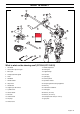
WHAT IS WHAT? 8 3 32 31 5 17 9 7 33 4 10 18 19 6 13 35 11 20 22 1 23 12 14 34 15 34 4 21 4 21 3 16 36 2 2 25 26 30 27 28 29 24 What is what on the clearing saw? (BC 2145) 1 Grass blade 19 Support cup 2 Grease filler cap, bevel gear 20 Support flange 3 Bevel gear 21 Drive disc 4 Cutting attachment guard 22 Trimmer head 5 Shaft 23 Spark plug 6 Handlebar 24 Socket spanner 7 Throttle control 25 Operator’s manual 8 Stop switch 26 Transport guard for cutting eq
WHAT IS WHAT? 3 8 7 18 5 9 17 4 10 30 13 18 19 11 6 21 1 14 12 15 20 4 16 23 31 3 2 29 22 24 28 25 26 27 What is what on the clearing saw? (FC 2145, FC 2145 S) 1 Saw blade 17 Handle adjustment 2 Grease filler cap, bevel gear 18 Locking nut 3 Bevel gear 19 Support flange 4 Cutting attachment guard 20 Drive disc 5 Shaft 21 Spark plug 6 Handlebar 22 Socket spanner 7 Throttle control 23 Operator’s manual 8 Stop switch 24 Transport guard for cutting equipment 9 Throt
GENERAL SAFETY PRECAUTIONS Important IMPORTANT! HELMET A helmet should be worn if the trees being cleared are taller than 2 m. The machine is only designed for trimming grass, grass clearing and/or forestry clearing. The only accessories you can operate with this engine unit are the cutting attachments we recommend in the chapter on Technical data.
GENERAL SAFETY PRECAUTIONS Machine′s safety equipment Press the throttle lock and make sure it returns to its original position when you release it. This section describes the machine′s safety equipment, its purpose, and how checks and maintenance should be carried out to ensure that it operates correctly. See the ”What is what?” section to locate where this equipment is positioned on your machine.
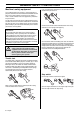
GENERAL SAFETY PRECAUTIONS Cutting attachment guard ! This guard is intended to prevent loose objects from being thrown towards the operator. The guard also protects the operator from accidental contact with the cutting attachment. WARNING! Overexposure to vibration can lead to circulatory damage or nerve damage in people who have impaired circulation. Contact your doctor if you experience symptoms of overexposure to vibration.
GENERAL SAFETY PRECAUTIONS Never use a machine that has a faulty muffler. Locking screw The lock screw must be tightened securely for ball-bearingmounted support cups. Regularly check that the muffler is securely attached to the machine. If the muffler on your machine is fitted with a spark arrestor mesh this must be cleaned regularly. A blocked mesh will cause the engine to overheat and may lead to serious damage.
GENERAL SAFETY PRECAUTIONS Cutting equipment General rules This section describes how to choose and maintain your cutting equipment in order to: • Reduce the risk of blade thrust. • Obtain maximum cutting performance. • Extend the life of cutting equipment. Only use cutting attachments with the guards we recommend! See the chapter on Technical data. IMPORTANT! Only use cutting attachments with the guards we recommend! See the chapter on Technical data.
GENERAL SAFETY PRECAUTIONS Sharpening the saw blade Trimmer head IMPORTANT! • A correctly sharpened blade is essential for working efficiently and to avoid unnecessary wear to the blade and clearing saw. • • Always ensure the trimmer cord is wound tightly and evenly around the drum, otherwise the machine will generate harmful vibration. See the cutting attachment packaging for correct sharpening instructions. • Only use the recommended trimmer heads and trimmer cords.
ASSEMBLY Assembling the handlebar and throttle Assembling the handlebar and throttle (BC 2145) (FC 2145, FC 2145 S) • Remove the screw at the rear of the throttle handle. • Slide the throttle handle onto the right side of the handlebar, (see diagram). • Unscrew the knob from the handlebar mounting. • Position the handlebar as shown. Fit the mounting components and tighten the knob lightly. Fit the right handle to the handlebar using the screw, washer, sleeve and nut as shown. Tighten.
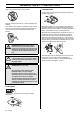
ASSEMBLY Fitting blades and trimmer heads • When fitting the cutting attachment it is extremely important that the raised section on the drive disc/support flange engages correctly in the centre hole of the cutting attachment. If the cutting attachment is fitted incorrectly it can result in serious and/or fatal personal injury. Fit the support flange (F) on the output shaft so that it rests against the blade. N E F D P B C A M L ! WARNING! Never use a cutting attachment without an approved guard.
ASSEMBLY Fitting the blade guard and saw blade Fitting the trimmer guard and trimmer head Trimmy SII • • Fit the correct trimmer guard (A) for use with the trimmer head. Hang the trimmer guard/combination guard (A) on the two hooks on the plate holder (M). Bend the guard around the shaft and tighten it with the bolt (L) on the opposite side of the shaft. Use the locking pin (C). Place the locking pin in the groove on the screw head and tighten. See diagram.
ASSEMBLY Fitting other guards and cutting attachments Fit the trimmer guard/combination guard (A) intended for use with the trimmer head/plastic blades. Hang the trimmer guard/combination guard (A) on the two hooks on the plate holder (M). Bend the guard around the shaft and tighten it with the bolt (L) on the opposite side of the shaft. Use the locking pin (C). Place the locking pin in the groove on the screw head and tighten. See diagram.
ASSEMBLY 2 Grass clearing 4 Adjust the height of the suspension hook as described in the instructions for the standard harness. (Forestry clearing) 5 If you need to lower the suspension hook, for trimming for example, move the suspension strap (A) to the lower mounting point on the backplate. 6 The elastic strap (B) can be tightened to transfer more load from the shoulder straps to the hip strap.
FUEL HANDLING Fuel safety Gasoline Never start the machine: 1 If you have spilt fuel on it. Wipe off the spillage and allow remaining fuel to evaporate. 2 If you have spilt fuel on yourself or your clothes, change your clothes. Wash any part of your body that has come in contact with fuel. Use soap and water. 3 If the machine is leaking fuel. Check regularly for leaks from the fuel cap and fuel lines.
FUEL HANDLING Mixing • Always mix the gasoline and oil in a clean container intended for fuel. • Always start by filling half the amount of the gasoline to be used. Then add the entire amount of oil. Mix (shake) the fuel mixture. Add the remaining amount of gasoline. • Mix (shake) the fuel mixture thoroughly before filling the machine’s fuel tank. • Do not mix more than one month’s supply of fuel at a time. • If the machine is not used for some time the fuel tank should be emptied and cleaned.
STARTING AND STOPPING Check before starting • • Check the blade to ensure that no cracks have formed at the bottom of the teeth or by the centre hole. The most common reason why cracks are formed is that sharp corners have been formed at the bottom of the teeth while sharpening or that the blade has been used with dull teeth. Discard a blade if cracks are found. Check that the support flange is not cracked due to fatigue or due to being tightened too much. Discard the support flange if it is cracked.
STARTING AND STOPPING If the machine is fitted with a decompression valve (A): Press the valve to reduce the pressure in the cylinder and make starting easier. You should always use the decompression valve when starting the machine. Once the machine has started the valve will automatically return to its original setting. Starting Hold the body of the machine on the ground using your left hand (CAUTION! Not with your foot!).
WORKING TECHNIQUES General working instructions IMPORTANT! 5 Switch off the engine before moving to another area. Fit the transport guard before carrying or transporting the equipment any distance. 6 Never put the machine down with the engine running unless you have it in clear sight. This section describes the basic safety precautions for working with clearing saws and trimmers. If you encounter a situation where you are uncertain how to proceed you should ask an expert.
WORKING TECHNIQUES Working methods ! • To fell to the left, the bottom of the tree should be pushed to the right. Tilt the blade and bring it diagonally down to the right, exerting firm pressure. At the same time push the stem using the blade guard. Cut with the area of the blade between 3 o’clock and 5 o’clock. Apply full throttle before advancing the blade. • To fell to the right, the bottom of the tree should be pushed to the left. Tilt the blade and bring it diagonally up to the right.
WORKING TECHNIQUES Brush cutting with a saw blade Grass clearing using a grass blade • Thin stems and brush are mown down. Work with a sawing movement, swinging sideways. • Grass blades and grass cutters must not be used on woody stems. • Try to cut several stems in a single sawing movement. • A grass blade is used for all types of tall or coarse grass. • With groups of hardwood stems, first clear around the group.
WORKING TECHNIQUES Grass trimming with a trimmer head Sweeping • The fan effect of the rotating cord can be used for quick and easy clearing up. Hold the cord parallel to and above the area to be swept and move the tool to and fro. • When cutting and sweeping you should use full throttle to obtain the best results. Trimming • Hold the trimmer head just above the ground at an angle. It is the end of the cord that does the work. Let the cord work at its own pace.
MAINTENANCE Carburetor Your Jonsered product has been designed and manufactured to specifications that reduce harmful exhaust fumes. The engine will be run in after it has used 8-10 tanks of fuel. To ensure that the engine runs at peak performance and produces as little harmful exhaust fumes as possible after the running-in period, ask your dealer/service workshop (which has a rev counter for this purpose) to adjust your carburettor.
MAINTENANCE Fine adjustment of the idle speed T Correctly adjusted carburetor Adjust the idle speed using the idle adjustment screw T, if it is necessary to readjust. First turn the idle adjustment screw T clockwise until the cutting attachment starts to rotate. Then turn the screw anticlockwise until the cutting attachment stops. The idle speed is correctly adjusted when the engine will run smoothly in every position.
MAINTENANCE Muffler Cooling system CAUTION! Some mufflers are fitted with a catalytic converter. See chapter on Technical data to see whether your machine is fitted with a catalytic converter. To keep the working temperature as low as possible the machine is equipped with a cooling system. 4 The muffler is designed to reduce the noise level and to direct the exhaust gases away from the operator.
MAINTENANCE Cleaning the air filter Bevel gear Remove the air filter cover and take out the filter. Wash it clean in warm, soapy water. The bevel gear is filled with the right amount of grease at the factory. However, before using the machine you should check that the bevel gear is filled 3/4 full with grease. Use JONSERED special grease. The grease in the bevel gear does not normally need to be changed except if repairs are carried out.
MAINTENANCE Winter use Running problems can occur when using the machine in the cold and snowy conditions caused by: • Too low engine temperature. • Icing of the air filter and carburetor. Special measures are therefore often required: • Partly mask the air inlet on the starter to increase the working temperature of the engine. • Preheat the intake air to the carburetor by using the heat from the cylinder.
MAINTENANCE Maintenance schedule The following is a list of the maintenance that must be performed on the machine. Most of the items are described in the Maintenance section. The user must only carry out the maintenance and service work described in this manual. More extensive work must be carried out by an authorised service workshop. Maintenance Daily maintenance Clean the outside of the machine. X Check that the harness is not damaged.
TECHNICAL DATA Technical data BC 2145 FC 2145 FC 2145 S 2,75/45 2,75/45 2,62/43 Engine Cylinder displacement, cu.in/cm3 Cylinder bore, inch/mm 1,65/42 1,65/42 1,61/41 Stroke, inch/mm 1,26/32 1,26/32 1,26/32 Idle speed, rpm 2800 2800 2800 Recommended max. speed, rpm 12500 13500 13500 Speed of output shaft, rpm 9000 10500 10500 Max. engine output, acc.
TECHNICAL DATA Approved accessories Type Centre hole in blades/cutters Ø 20 mm: FC Ø 1”: BC Output shaft thread M12 Grass blade/grass cutter Saw blade Plastic blades Trimmer head Support cup Cutting attachment guard, Art. no.
FEDERAL EMISSION CONTROL WARRANTY STATEMENT YOUR WARRANTY RIGHTS AND OBLIGATIONS rights and responsibilities, you should contact your nearest authorized servicing dealer or call Jonsered, at Sweden +4636-146500. The EPA (The US Environmental Protection Agency), Environment Canada and Jonsered are pleased to explain the emissions control system warranty on your 2001 and later small nonroad engine. In U.S.
Poly Trim 1 B <20mm 2 A 3 4 5 >20mm 6 8 7 6 Nm ! X 10
Trimmy SII 1 2,4-3,3 mm .095"-.
Auto 55 1 2 3 >1,1 Kw 1.) <1,1 Kw 2.) 2,7-3,3 mm .106-.
Tap n’Go 45 2 3 2,7-3,3 mm .106-.
1088930-95 ´®z*x})¶5¢¨ ´®z*x})¶5¢¨ 2004-07-01