Operator’s manual (EPA) Please read the operator’s manual carefully and make sure you understand the instructions before using the machine.
KEY TO SYMBOLS Symbols Always wear approved protective gloves. WARNING! Clearing saws, brushcutters and trimmers can be dangerous! Careless or incorrect use can result in serious or fatal injury to the operator or others. Regular cleaning is required. Please read the operator’s manual carefully and make sure you understand the instructions before using the machine. Visual check.
CONTENTS Contents KEY TO SYMBOLS Symbols ....................................................................... CONTENTS Contents ...................................................................... Note the following before starting: ................................ INTRODUCTION Dear customer! ............................................................ WHAT IS WHAT? What is what on the clearing saw? (BC 2145) .............. What is what on the clearing saw? (FC 2145, FC 2145 S, FC 2145 W) .............
INTRODUCTION Dear customer! Congratulations on your choice to buy a Jonsered product! Your purchase gives you access to professional help with repairs and service whenever this may be necessary. If the retailer who sells your machine is not one of our authorized dealers, ask for the address of your nearest servicing dealer. It is our wish that you will be satisfied with your product and that it will be your companion for a long time. Think of this operator′s manual as a valuable document.
WHAT IS WHAT? 3 8 32 31 5 17 9 7 33 10 4 18 35 19 6 13 11 20 22 1 23 34 14 34 4 21 3 12 15 4 21 16 36 2 2 25 26 30 27 28 29 24 What is what on the clearing saw? (BC 2145) 1 Grass blade 19 Support cup 2 Grease filler cap, bevel gear 20 Support flange 3 Bevel gear 21 Drive disc 4 Cutting attachment guard 22 Trimmer head 5 Shaft 23 Spark plug cap and spark plug 6 Handlebar 24 Socket spanner 7 Throttle control 25 Operator’s manual 8 Stop switch 26 Transport
WHAT IS WHAT? 8 3 7 8 7 18 5 9 32 9 17 4 10 30 13 18 19 11 6 21 1 14 12 15 20 4 16 23 31 3 2 29 22 24 28 25 26 27 What is what on the clearing saw? (FC 2145, FC 2145 S, FC 2145 W) 1 Saw blade 17 Handle adjustment 2 Grease filler cap, bevel gear 18 Locking nut 3 Bevel gear 19 Support flange 4 Cutting attachment guard 20 Drive disc 5 Shaft 21 Spark plug 6 Handlebar 22 Socket spanner 7 Throttle control 23 Operator’s manual 8 Stop switch 24 Transport guard for cutt
GENERAL SAFETY PRECAUTIONS Important IMPORTANT! HELMET A helmet should be worn if the trees being cleared are taller than 2 m. The machine is only designed for trimming grass, grass clearing and/or forestry clearing. The only accessories you can operate with this engine unit are the cutting attachments we recommend in the chapter on Technical data.
GENERAL SAFETY PRECAUTIONS Machine′s safety equipment Press the throttle lock and make sure it returns to its original position when you release it. This section describes the machine′s safety equipment, its purpose, and how checks and maintenance should be carried out to ensure that it operates correctly. See the ”What is what?” section to locate where this equipment is positioned on your machine.
GENERAL SAFETY PRECAUTIONS Cutting attachment guard This guard is intended to prevent loose objects from being thrown towards the operator. The guard also protects the operator from accidental contact with the cutting attachment. Check that the guard is undamaged and not cracked. Replace the guard if it has been exposed to impact or is cracked. Always use the recommended guard for the cutting attachment you are using. See chapter on Technical data.
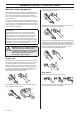
GENERAL SAFETY PRECAUTIONS For mufflers it is very important that you follow the instructions on checking, maintaining and servicing your machine. See instructions under the heading Checking, maintaining and servicing the machine’s safety equipment. Never use a machine that has a faulty muffler. When loosening and tightening the saw blade nut, there is a risk of injury from the teeth of the saw blade. You should therefore always ensure that your hand is shielded by the blade guard when doing this.
GENERAL SAFETY PRECAUTIONS ! ! WARNING! Always stop the engine before doing any work on the cutting attachment. This continues to rotate even after the throttle has been released. Ensure that the cutting attachment has stopped completely and disconnect the HT lead from the spark plug before you start to work on it. WARNING! Using an incorrect cutting attachment or an incorrectly sharpened blade increases the risk of kickback. Check the cutting attachment for damage or cracks.
GENERAL SAFETY PRECAUTIONS • The filing angle is 15°. File alternate teeth to the right and those in between to the left. If the blade has been heavily pitted by stones it may be necessary to dress the top edges of the teeth with a flat file, in exceptional cases. If so, this should be done before filing with a round file. The top edges must be filed down by the same amount for all the teeth. Adjust the blade setting. This should be 1 mm.
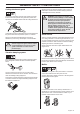
ASSEMBLY Assembling the handlebar and throttle Assembling the handlebar and throttle (BC 2145) (FC 2145, FC 2145 S, FC 2145 W) • Remove the screw at the rear of the throttle handle. • Unscrew the knob from the handlebar mounting. • Slide the throttle handle onto the right side of the handlebar, (see diagram). • Position the handlebar as shown. Fit the mounting components and tighten the knob lightly. Fit the right handle to the handlebar using the screw, washer, sleeve and nut as shown. Tighten.
ASSEMBLY Assembling the cutting equipment ! WARNING! When fitting the cutting attachment it is extremely important that the raised section on the drive disc/support flange engages correctly in the centre hole of the cutting attachment. If the cutting attachment is fitted incorrectly it can result in serious and/or fatal personal injury. • Position the blade (D) with the drive disk (B). Make sure that the blade is centered by fitting it to the guide on the drive disk.
ASSEMBLY • Turn the blade shaft until one of the holes in the drive disc aligns with the corresponding hole in the gear housing. • Insert the locking pin (C) in the hole to lock the shaft. • Place the blade (D) and support flange (F) on the output shaft. G • Turn the blade shaft until one of the holes in the drive disc aligns with the corresponding hole in the gear housing.
ASSEMBLY Adjusting the harness and clearing saw ! 2 Grass clearing The machine should be supported in a harness when grass clearing so that the cutting equipment is parallel to the ground. WARNING! When using a clearing saw it must always be hooked securely to the harness. Otherwise you will be unable to control the clearing saw safely and this can result in injury to yourself or others. Never use a harness with a defective quick release.
ASSEMBLY 4 Adjust the height of the suspension hook as described in the instructions for the standard harness. (Forestry clearing) 5 If you need to lower the suspension hook, for trimming for example, move the suspension strap (A) to the lower mounting point on the backplate. 6 The elastic strap (B) can be tightened to transfer more load from the shoulder straps to the hip strap.
FUEL HANDLING Fuel safety Gasoline Never start the machine: 1 If you have spilt fuel on it. Wipe off the spillage and allow remaining fuel to evaporate. 2 If you have spilt fuel on yourself or your clothes, change your clothes. Wash any part of your body that has come in contact with fuel. Use soap and water. 3 If the machine is leaking fuel. Check regularly for leaks from the fuel cap and fuel lines.
FUEL HANDLING Fueling Mixing • Always mix the gasoline and oil in a clean container intended for fuel. • Always start by filling half the amount of the gasoline to be used. Then add the entire amount of oil. Mix (shake) the fuel mixture. Add the remaining amount of gasoline. • ! Mix (shake) the fuel mixture thoroughly before filling the machine’s fuel tank. WARNING! Taking the following precautions, will lessen the risk of fire: Do not smoke or place hot objects near fuel.
STARTING AND STOPPING Check before starting • Check the blade to ensure that no cracks have formed at the bottom of the teeth or by the centre hole. The most common reason why cracks are formed is that sharp corners have been formed at the bottom of the teeth while sharpening or that the blade has been used with dull teeth. Discard a blade if cracks are found.
STARTING AND STOPPING Start throttle: (FC 2145, FC 2145 S, FC 2145 W, BC 2145) Heated handles Set the throttle to the start position by moving the choke control to the choke position and then returning it to its original position. (FC 2145 W) If the machine is fitted with a decompression valve (A): Press the valve to reduce the pressure in the cylinder and make starting easier. You should always use the decompression valve when starting the machine.
WORKING TECHNIQUES General working instructions 6 Always hold the machine with both hands. Hold the machine on the right side of your body. 7 Keep the cutting attachment below waist level. 8 Switch off the engine before moving to another area. Fit the transport guard before carrying or transporting the equipment any distance. 9 Never put the machine down with the engine running unless you have it in clear sight.
WORKING TECHNIQUES ! WARNING! Sometimes branches or grass get caught between the guard and cutting attachment. Always stop the engine before cleaning. Working methods ! Forestry clearing using a saw blade • The risk of kickback increases with increasing stem size. You should therefore avoid cutting with the area of the blade between 12 o’clock and 3 o’clock. • To fell to the left, the bottom of the tree should be pushed to the right.
WORKING TECHNIQUES • Large stems must be cut from two sides. First determine which direction the stem will fall. Make the first cut on the felling side. Then finish cutting the stem from the other side. Adjust the cutting pressure to match the size of the stem and the hardness of the wood. Small stems require more pressure, while large stems require less pressure. • If the stems are tightly packed, adapt your walking pace to suit. • If the blade jams in a stem, never jerk the machine free.
WORKING TECHNIQUES Clearing • The clearing technique removes all unwanted vegetation. Keep the trimmer head just above the ground and tilt it. Let the end of the cord strike the ground around trees, posts, statues and the like. CAUTION! This technique increases the wear on the cord. • The cord wears quicker and must be fed forward more often when working against stones, brick, concrete, metal fences, etc., than when coming into contact with trees and wooden fences.
MAINTENANCE Carburetor Basic setting Your Jonsered product has been designed and manufactured to specifications that reduce harmful exhaust fumes. The engine will be run in after it has used 8-10 tanks of fuel. To ensure that the engine runs at peak performance and produces as little harmful exhaust fumes as possible after the running-in period, ask your dealer/service workshop (which has a rev counter for this purpose) to adjust your carburettor.
MAINTENANCE Fine adjustment of the idle speed T Adjust the idle speed using the idle adjustment screw T, if it is necessary to readjust. First turn the idle adjustment screw T clockwise until the cutting attachment starts to rotate. Then turn the screw anticlockwise until the cutting attachment stops. The idle speed is correctly adjusted when the engine will run smoothly in every position. The idle speed should also be well below the speed at which the cutting attachment starts to rotate.
MAINTENANCE Adjusting the start throttle speed (BC 2145) The correct start throttle speed is set by means of an adjuster on the rear of the handle next to the cable. Use this screw (5 mm Allen screw) to increase or decrease the start throttle speed. If the mesh is frequently blocked, this can be a sign that the performance of the catalytic converter is impaired. Contact your dealer to inspect the muffler. A blocked mesh will cause the machine to overheat and result in damage to the cylinder and piston.
MAINTENANCE Air filter Bevel gear The air filter must be regularly cleaned to remove dust and dirt in order to avoid: The bevel gear is filled with the right amount of grease at the factory. However, before using the machine you should check that the bevel gear is filled 3/4 full with grease. Use JONSERED special grease. • Carburettor malfunctions • Starting problems • Loss of engine power • Unnecessary wear to engine parts • Excessive fuel consumption.
MAINTENANCE Winter use Running problems can occur when using the machine in the cold and snowy conditions caused by: • Too low engine temperature. • Icing of the air filter and carburetor. Special measures are therefore often required: • Partly mask the air inlet on the starter to increase the working temperature of the engine. • Preheat the intake air to the carburetor by using the heat from the cylinder.
MAINTENANCE Maintenance schedule The following is a list of the maintenance that must be performed on the machine. Most of the items are described in the Maintenance section. The user must only carry out the maintenance and service work described in this manual. More extensive work must be carried out by an authorised service workshop. Maintenance Daily maintenance Clean the outside of the machine. X Check that the harness is not damaged.
TECHNICAL DATA Technical data BC 2145 FC 2145 FC 2145 S FC 2145 W Cylinder displacement, cu.in/cm3 2,75/45 2,75/45 2,62/43 2,62/43 Cylinder bore, inch/mm 1,65/42 1,65/42 1,61/41 1,61/41 Stroke, inch/mm 1,26/32 1,26/32 1,26/32 1,26/32 Idle speed, rpm 2800 2800 2800 2800 Recommended max. speed, rpm 12500 13500 13500 13500 Speed of output shaft, rpm 9000 Engine 10500 10500 10500 Max. engine output, acc.
TECHNICAL DATA BC 2145 Approved accessories Type Cutting attachment guard, Art. no.
FEDERAL EMISSION CONTROL WARRANTY STATEMENT YOUR WARRANTY RIGHTS AND OBLIGATIONS The EPA (The US Environmental Protection Agency), Environment Canada and Jonsered are pleased to explain the emissions control system warranty on your 2001 and later small nonroad engine. In U.S. and Canada, new small nonroad engines must be designed, built and equipped to meet the federal stringent anti-smog standards.
Poly Trim 1 B <20mm 2 A 3 4 5 >20mm 6 8 7 6 Nm ! X 10
Trimmy SII 1 2,4-3,3 mm .095"-.
Auto 55 1 2 3 >1,1 Kw 1.) <1,1 Kw 2.) 2,7-3,3 mm .106-.
Tap n’Go 45 2 3 2,7-3,3 mm .106-.
1150102-95 ´®z+R*=¶5`¨ ´®z+R*=¶5`¨ 2005-09-29