Operator’s manual (EPA) Please read the operator’s manual carefully and make sure you understand the instructions before using the machine.
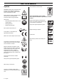
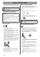
KEY TO SYMBOLS Symbols Only intended for trimmer heads. WARNING! Clearing saws, brushcutters and trimmers can be dangerous! Careless or incorrect use can result in serious or fatal injury to the operator or others. Please read the operator’s manual carefully and make sure you understand the instructions before using the machine. Other symbols/decals on the machine refer to special certification requirements for certain markets.
CONTENTS Contents KEY TO SYMBOLS Symbols ....................................................................... CONTENTS Contents ...................................................................... Note the following before starting: ................................ SAFETY INSTRUCTIONS Personal protective equipment ..................................... Machine′s safety equipment ........................................ Checking, maintaining and servicing the machine′s safety equipment ..................
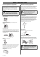
SAFETY INSTRUCTIONS Personal protective equipment IMPORTANT! You must use approved personal protective equipment whenever you use the machine. Personal protective equipment cannot eliminate the risk of injury but it will reduce the degree of injury if an accident does happen. Ask your dealer for help in choosing the right equipment. ! WARNING! Listen out for warning signals or shouts when you are wearing hearing protection. Always remove your hearing protection as soon as the engine stops.
SAFETY INSTRUCTIONS Vibration damping system Your machine is equipped with a vibration damping system that is designed to reduce vibration and make operation easier. For mufflers it is very important that you follow the instructions on checking, maintaining and servicing your machine. See instructions under the heading Checking, maintaining and servicing the machine’s safety equipment. ! Use of incorrectly wound cord or an incorrect cutting attachment increases the level of vibration.
SAFETY INSTRUCTIONS Checking, maintaining and servicing the machine′s safety equipment IMPORTANT! All servicing and repair work on the machine requires special training. This is especially true of the machine′s safety equipment. If your machine fails any of the checks described below you must contact your service agent. When you buy any of our products we guarantee the availability of professional repairs and service.
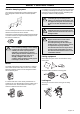
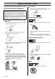
SAFETY INSTRUCTIONS • • Regularly check that the muffler is securely attached to the machine. Locking nut • When fitting, tighten the nut in the opposite direction to the direction of rotation of the cutting attachment. To remove it, undo the nut in the same direction as the cutting attachment rotates. (CAUTION! The nut has a left-hand thread.) • Tighten the nut using the socket spanner. 35-50 Nm (3.55 kpm).
SAFETY INSTRUCTIONS Cutting equipment IMPORTANT! Trimmer head • Only use the recommended trimmer heads and trimmer cords. These have been tested by the manufacturer to suit a particular engine size. This is especially important when a fully automatic trimmer head is used. Only use the recommended cutting attachment. See the chapter on Technical data. • Smaller machines generally require small trimmer heads and vice versa.
SAFETY INSTRUCTIONS General safety precautions • IMPORTANT! The machine is only designed for trimming grass, grass clearing and/or forestry clearing. Place the machine on the ground, ensure the cutting attachment is clear of twigs and stones. Hold the body of the machine on the ground using your left hand (CAUTION! Not with your foot). Then grip the starter handle with your right hand and pull the starter cord.
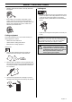
SAFETY INSTRUCTIONS • The transport guard must always be fitted to the cutting attachment when the machine is being transported or in storage. ! WARNING! Take care when handling fuel. Bear in mind the risk of fire, explosion and inhaling fumes. Basic working techniques • Always slow the engine to idle speed after each working operation. Long periods at full throttle without any load on the engine can lead to serious engine damage. Terms • Use a grass cutter or grass blade for clearing grass.
SAFETY INSTRUCTIONS Grass trimming using a trimmer head and plastic blades • Trimming Do not allow the trimmer head to constantly come into contact with the ground during normal cutting. Constant contact of this type can cause damage and wear to the trimmer head. Sweeping • • • Hold the trimmer head just above the ground at an angle. It is the end of the cord that does the work. Let the cord work at its own pace. Never press the cord into the area to be cut.
WHAT IS WHAT? 30 What is what on the trimmer? 1 Trimmer head 16 Handle adjustment 2 Grease filler cap, bevel gear 17 Locking nut 3 Bevel gear 18 Support flange 4 Cutting attachment guard 19 Drive disc 5 Shaft 20 Socket spanner 6 Loop handle 21 Operator’s manual (EPA) 7 Throttle control 22 Allen key 8 Stop switch 23 Locking pin 9 Throttle lock 24 Support cup 10 Cylinder cover 25 Blade 11 Starter handle 26 Transport guard 12 Fuel tank 27 J-handle 13 Choke control 28 Support
ASSEMBLY Fitting the loop handle (GT 2125) • • Slide the spacer into the slot in the loop handle. • Fit the nut, knob and screw. Do not overtighten. • Attach the J-handle to the loop handle using the three screws, as shown. • Now adjust the trimmer to give a comfortable working position. Tighten the bolt/knob. Position the handle on the shaft. Note that the handle must be mounted below the arrow on the shaft. • Fit the screw, securing plate and wing nut as shown in the diagram.
ASSEMBLY Fitting the trimmer guard and Auto 32 trimmer head Fitting the blade guard/combination guard, grass blade and grass cutter (GC 2125) (GC 2125) • K G F I K J Hook the blade guard/combination guard (A) onto the fitting on the shaft and secure with the bolt. CAUTION! Use the recommended blade guard. See the Technical data section. B C I G F E D A A • Fit the correct trimmer guard (A) for use with the trimmer head.
ASSEMBLY Fitting other guards and cutting attachments Fitting the trimmer guard and trimmer head (GC 2125) (GT 2125) • Fit the correct trimmer guard (A) for use with the trimmer head. Hook the trimmer guard/combination guard onto the fitting on the shaft and secure with the bolt (L). A Guard • Fit the guard as shown in the diagram. Tighten securely. Trimmer head • Fit the drive disc (B) on the output shaft.
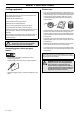
FUEL HANDLING Fuel Two-stroke oil CAUTION! The machine is equipped with a two-stroke engine and must always been run using a mixture of gasoline and two-stroke engine oil. It is important to accurately measure the amount of oil to be mixed to ensure that the correct mixture is obtained. When mixing small amounts of fuel, even small inaccuracies can drastically affect the ratio of the mixture.
FUEL HANDLING Fueling ! WARNING! Taking the following precautions, will lessen the risk of fire: Do not smoke or place hot objects near fuel. Always shut off the engine before refuelling. Always stop the engine and let it cool for a few minutes before refuelling. When refuelling, open the fuel cap slowly so that any excess pressure is released gently. Tighten the fuel cap carefully after refuelling. Always move the machine away from the refuelling area before starting.
STARTING AND STOPPING Check before starting • • Check that the support flange is not cracked due to fatigue or due to being tightened too much. Discard the support flange if it is cracked. Starting and stopping ! WARNING! The complete clutch cover and shaft must be fitted before the machine is started, otherwise the clutch can come loose and cause personal injury. Always move the machine away from the refuelling area before starting. Place the machine on a flat surface.
STARTING AND STOPPING some resistance (the starter pawls grip), now quickly and powerfully pull the cord. Never wrap the starter cord around your hand Repeat pulling the cord until the engine starts. When the engine starts. return choke control to run position and apply full throttle; the throttle will automatically disengage from the start setting. CAUTION! Do not pull the starter cord all the way out and do not let go of the starter handle when the cord is fully extended. This can damage the machine.
MAINTENANCE Carburetor Basic setting Your Jonsered product has been designed and manufactured to specifications that reduce harmful exhaust fumes. The engine will be run in after it has used 8-10 tanks of fuel. To ensure that the engine runs at peak performance and produces as little harmful exhaust fumes as possible after the running-in period, ask your dealer/service workshop (which has a rev counter for this purpose) to adjust your carburettor.
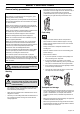
MAINTENANCE Fine adjustment of the idle speed T Correctly adjusted carburetor Adjust the idle speed using the idle adjustment screw T, if it is necessary to readjust. First turn the idle adjustment screw T clockwise until the cutting attachment starts to rotate. Then turn the screw anticlockwise until the cutting attachment stops. The idle speed is correctly adjusted when the engine will run smoothly in every position.
MAINTENANCE Cooling system Air filter To keep the working temperature as low as possible the machine is equipped with a cooling system. The cooling system consists of: 1 Air intake on the starter. The air filter must be regularly cleaned to remove dust and dirt in order to avoid: 2 Fins on the flywheel. • Carburettor malfunctions 3 Cooling fins on the cylinder. • Starting problems 4 Cylinder cover (directs cold air over the cylinder).
MAINTENANCE Spark plug • Check that there are no fuel leaks from the engine, tank or fuel lines. Weekly maintenance The spark plug condition is influenced by: • Check the starter and starter cord. • Incorrect carburetor adjustment. • Clean the outside of the carburetor. • An incorrect fuel mixture (too much or incorrect type of oil). • • A dirty air filter. Clean the outside of the spark plug. Remove it and check the electrode gap. Adjust the gap to 0.5 mm (.20”), or replace the spark plug.
TECHNICAL DATA Technical data Technical data GT 2125 GC 2125 1,50/24,5 1,50/24,5 Engine Cylinder displacement, cu.in/cm3 Cylinder bore, inch/mm 1,28/32 1,28/32 Stroke, inch/mm 1,06/27 1,06/27 Idle speed, rpm 2700 2700 Recommended max. speed, rpm 11000-11700 11000-11700 Speed of output shaft, rpm 11700 8014 Max. engine output, acc.
TECHNICAL DATA Approved accessories Type Cutting attachment guard, Art. no.
FEDERAL EMISSION CONTROL WARRANTY STATEMENT YOUR WARRANTY RIGHTS AND OBLIGATIONS rights and responsibilities, you should contact your nearest authorized servicing dealer or call Jonsered, at Sweden +4636-146500. The EPA (The US Environmental Protection Agency), Environment Canada and Jonsered are pleased to explain the emissions control system warranty on your 2001 and later small nonroad engine. In U.S.
Trimmy H II 1 2 3 4 2,0-2,4 mm .080-.
S35 2 3 2,4-2,7 mm .095-.
S35 3 2 2,4-2,7 mm .095-.
Tap-N-Go 35 2 3 2,4-2,7 mm .095-.
Auto 32 1 2 3 4 2,4 mm .
1088931-95 ´®z*x}3¶5U¨ ´®z*x}3¶5U¨ 2004-06-14