Operator´s manual (EPA) Please read these instructions carefully and make sure you understand them before using the machine.
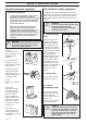
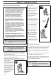
SYMBOL EXPLANATION Symbols WARNING! Clearing saws, brushcutters and trimmers can be dangerous! Careless or incorrect use can result in serious or fatal injury to the operator or others. Only use non-metallic, flexible cutting elements, that is trimmer head with trimmer cord. Always use • A protective helmet where there is a risk of falling objects • Ear protection • Approved eye protection Only intended for the trimmer head. This product is in accordance with applicable CE directives.
CONTENTS Jonsered has a policy of continuous product development and therefore reserves the right to modify the design and appearance of products without prior notice. Maintenance, replacement, or repair of the emission control devices and systems may be performed by any nonroad engine repair establishment or individual. ! WARNING! Under no circumstances may the design of the machine be modified without the permission of the manufacturer. Always use genuine accessories.
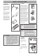
SAFETY INSTRUCTIONS Personal protective equipment MPORTANT INFORMATION • • A clearing saw, brushcutter or trimmer used incorrectly or carelessly can become a dangerous tool, that can cause serious or fatal injury to the operator or others. It is extremely important that you read and understand the content of this manual. When using a trimmer, personal protective equipment approved by the appropriate authorities must be used.
SAFETY INSTRUCTIONS 4. Vibration damping system Your machine is equipped with a vibration damping system, which is designed to give as vibration-free and comfortable use as possible. Use of incorrectly wound cord or incorrect cutting equipment increases the level of vibration. The machine’s vibration damping system reduces the transfer of vibrations between the engine unit/ cutting equipment and the machine’s handle unit. 5.
SAFETY INSTRUCTIONS Control, maintenance and service of the machine‘s safety equipment IMPORTANT INFORMATION • All service and repairs to the machine require special training. • This applies especially to the machine‘s safety equipment. If the machine does not meet any of the controls listed below you should contact your service workshop. • The purchase of one of our products guarantees that professional repair and servicing will be carried out on it.
SAFETY INSTRUCTIONS 6. Cutting equipment The section describes how through correct maintenance and through using the right type of cutting equipment you can: • Obtain maximum clearing capacity. • Increase the service life of the cutting equipment. Two basic rules: 1)Only use the cutting and guard equipment we recommend! See chapter “Technical data“. 2)Check the cutting equipment with regard to damage and crack formation. Damaged cutting equipment should always be replaced. 7.
SAFETY INSTRUCTIONS General safety instructions IMPORTANT INFORMATION • The machine is only designed for trimming grass. • The only accessories to be used with the engine unit as a drive source are the cutting units we recommend in the chapter “Technical data“. • Never use the machine if you are tired, if you have consumed alcohol, or if you are taking medicines that can affect your sight, your judgement or the control of your body. • Use personal protective equipment.
SAFETY INSTRUCTIONS General working instructions IMPORTANT INFORMATION • This section takes up the basic safety precautions for working with the trimmer. • If you encounter a situation where you are uncertain how to proceed you should ask an expert. Contact your dealer or your service workshop. • Avoid all usage which you consider to be beyond your capability. Basic working techniques • Always drop to idling speed after each working operation.
SAFETY INSTRUCTIONS Clearing • The clearing technique removes all unwanted vegetation. Keep the trimmer head just above the ground and tilt it. Let the end of the cord strike the ground around trees, posts, statues and the like. NOTE! This technique increases the wear on the cord. Trimming • The trimmer is ideal to cut grass that is difficult to reach using a normal lawn mower. Keep the cord parallel to the ground when cutting.
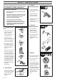
WHAT IS WHAT? J O N S E R E D S E R V I C E What is what on the trimmer? 1. 2. 3. 4. 5. 6. 7. 8. 9. 10. 11. 12. Trimmer head Grease filler cap Angle gear Spray guard Shaft Loop handlebar Throttle Stop switch Throttle trigger lock Cylinder cover Starter handle Fuel tank 13. Choke 14. Air purge 15. Air filter cover 16. Clutch cover 17. Handlebar adjustment 18. Locking nut 19. Support flange 20. Drive disc 21. Socket spanner 22. Operator‘s Manual 23. Allen key 24.
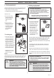
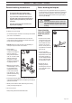
ASSEMBLY Assembling the loop handlebar (GT2125L) • Position the handle on the shaft. Note that the handle must be mounted below the arrow on the shaft. • Fit the bolt, securing plate and wing nut as shown in the diagram. Assembly of the trimmer head It is extremely important that the disc drive’s/support flange’s guide engages correctly in the cutting equipment’s centre hole when assembling the cutting equipment. Cutting equipment assembled incorrectly can result in serious and/or fatal personal injury.
ASSEMBLY Assembling the spray guard and trimmer head Auto 32 (GR2126L) Assembling other guards and cutting equipment (GR2126L) • Fit the guard (A) intended for use with the trimmer head. Hook the guard onto the shaft fitting and secure it with the bolt (L). • Fit the guard (A) intended for use with the trimmer head. Hook the guard onto the shaft fitting and secure it with the bolt (L). • Fit the drive disc (B) on the output axle.
FUEL HANDLING Fuel mixture NOTE! The machine is fitted with a two-stroke engine and must always be run on a mixture of petrol and two-stroke oil. It is important to measure the quantity of oil accurately, to ensure the correct mixture ratio. Small discrepancies in the amount of oil have a great bearing on the proportions of the fuel mixture when mixing small amounts of fuel. ! WARNING! Always provide good ventilation when handling fuel.
START AND STOP Control before starting For reasons of safety follow these recommendations! • Check that the support flange is not cracked due to fatigue or due to being tightened too much. Discard the support flange if it is cracked. • Ensure the locking nut has not lost its captive force. The nut lock should have a locking force of at least 1.5 Nm. The tightening torque of the locking nut should be 35-50 Nm. • Check that the trimmer head and spray guard are not damaged or cracked.
MAINTENANCE Carburettor Your JONSERED product has been designed and manufactured to specifications that reduce harmful emissions. After your unit has been run 8-10 tanks of fuel the engine has broken in. To ensure that your unit is at peak performance and producing the least amount of harmful emissions after break in, have your authorized servicing dealer, who has a revolution counter at his disposal, to adjust your carburettor for optimum operating conditions.
MAINTENANCE Final setting of the idling speed T Correctly adjusted carburettor Adjust the idling speed with the screw T, if it is necessary to readjust. First turn the idle speed adjusting screw T clockwise until the cutting attachment starts to rotate/ move. Then turn, counterclockwise until the cutting attachment stops. A correctly adjusted idle speed setting occurs when the engine runs smoothly in every position.
ENTRETIEN Silencieux Circuit de refroidissement NOTER! Certains silencieux sont dotés d’un pot catalytique. Voir ”Caractéristiques techniques” pour déterminer si la machine est pourvue d’un pot catalytique. Pour obtenir une température de service aussi basse que possible, le moteur est muni d’un circuit de refroidissement. Le système de refroidissement se compose de: 1. Prise d’air au niveau du démarreur. 2. Ailettes de ventilation sur la roue volante. 3. Ailettes de refroidissement sur le cylindre. 4.
MAINTENANCE Air filter The air filter should be cleaned regularly removing dust and dirt to avoid: • carburettor malfunction • starting problems • reduced engine power • unnecessary wear to engine parts • abnormal fuel consumption Clean the filter after every 25 hours or more regularly if operating conditions are exceptionally dusty. Cleaning the air filter Dismantle the air filter cover and remove the air filter. Wash in clean, warm soapy water. Ensure that the filter is dry before refitting.
TECHNICAL DATA Technical data GT2125L GR2126L Engine Displacement, cu. in/cm3 Cylinder bore, inch/mm Stroke length, inch/mm Recommended max. speed, rpm Idling speed, rpm Speed of output shaft, rpm Max. engine output, acc.
EMISSION CONTROL WARRANTY STATEMENT YOUR WARRANTY RIGHTS AND OBLIGATIONS The EPA (U.S. Environmental Protection Agency), Environment Canada and Jonsered are pleased to explain the emissions control system warranty on your 2001 and later small off-road engine. In U.S. and Canada, new small off-road engines must be designed, built and equipped to meet the federal stringent antismog standards.
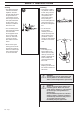
Poly Trim 1 B >20mm 2 A 3 4 5 >20mm 6 8 7 6 Nm ! X 10 22 – English
Trimmy H II 1 2 3 4 2,0-2,4 mm .080-.
Trimmy Hit Pro 2 3 2,0-2,4 mm .080-.095" 1 7,5 m 25' 4 15 cm 6" ~ 3,7 m 12' 5 6 7 9 8 15 cm 6" 11 10 12 1.) 2.
Trimmy VII 2 3 2,0- mm ,080-.
Tap-N-Go Pro 2 3 2,0-2,4 mm .080-.095" 1 7,5 m 25' 4 15 cm 6" ~ 3,7 m 12' 5 6 7 9 8 15 cm 6" 11 10 12 1.) 2.
108 88 48-95 ´*xty¶5s¨ 2002W11