02764 LT2220 CMA2 Operator's Manual
SAFETY RULES Safe Operation Practices for Ride-On Mowers DANGER: THIS CUTTING MACHINE IS CAPABLE OF AMPUTATING HANDS AND FEET AND THROWING OBJECTS. FAILURE TO OBSERVE THE FOLLOWING SAFETY INSTRUCTIONS COULD RESULT IN SERIOUS INJURY OR DEATH. • WARNING: In order to prevent accidental starting when setting up, transporting, adjusting or making repairs, always disconnect spark plug wire and place wire where it cannot contact spark plug.
SAFETY RULES Safe Operation Practices for Ride-On Mowers III. CHILDREN GENERAL SERVICE • Never operate machine in a closed area. • Keep all nuts and bolts tight to be sure the equipment is in safe working condition. • Never tamper with safety devices. Check their proper operation regularly. • Keep machine free of grass, leaves, or other debris build-up. Clean oil or fuel spillage and remove any fuelsoaked debris. Allow machine to cool before storing.
PRODUCT SPECIFICATIONS Gasoline Capacity and type: 2.0 Gallons Unleaded Regular Oil Type (API-SG-SL): SAE 30 (above 32°F) SAE 5W-30 (below 32°F) Oil Capacity: W/ Filter: 64 oz W/O Filter: 60 oz Spark Plug: Champion QC12YC (Gap: .040") Ground Speed (MPH): Forward: 0 – 5.2 Reverse: 0 – 2.9 Charging System: 16 AMPS @ 3600 RPM Battery: AMP/HR: 28 MIN. CCA: 230 CASE SIZE: U1R Blade Bolt Torque: CONGRATULATIONS on your purchase of a new tractor.
UNASSEMBLED PARTS Steering Steering Wheel Insert (1) Steering Wheel (1) Flat Washer Steering Wheel Adapter Steering Boot (1) Locknut Seat (1) Washer (1) Knob (1) Seat Keys Slope Sheet (1) Oil Drain Tube For Future Use (2) Keys 5
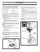
ASSEMBLY Your new tractor has been assembled at the factory with exception of those parts left unassembled for shipping purposes. To ensure safe and proper operation of your tractor all parts and hardware you assemble must be tightened securely. Use the correct tools as necessary to ensure proper tightness. TOOLS REQUIRED FOR ASSEMBLY ATTACH STEERING WHEEL (See Fig. 2) • A socket wrench set will make assembly easier. Standard wrench sizes are listed.
ASSEMBLY TO INSTALL BAGGER COMPONENTS TO TRACTOR (See Figs. 4A-4D) INSTALL SEAT (See Fig. 3) Adjust seat before tightening adjustment knob. • Remove adjustment knob and flat washer securing seat to cardboard packing and set aside for assembly of seat to tractor. • Pivot seat upward and remove from the cardboard packing. Remove the cardboard packing and discard. • Place seat on seat pan so head of shoulder bolt is positioned over large slotted hole in pan.
ASSEMBLY NOTE: The strap hook must go through the discharge chute only. Do not allow the hook to enter the slot in the tractor back plate. This will allow the discharge chute to float with the mower deck when moving on uneven terrain. DUMP HANDLE TUBE CLEVIS PIN 10 X 44MM RETAINER SPRING DISCHARGE CHUTE HOOK 7 90 02 CAP 0230 6 BACKPLATE SLOT Fig. 5C BAGGER ADJUSTMENT (See Fig. 6 & 7) Fig. 4D For proper bag function and appearance, it may be necessary to adjust the bagger assembly.
ASSEMBLY • • • CHECK FOR PROPER POSITION OF ALL BELTS After proper fit is attained, remove bagger from tractor and install bagger latch (4) to tractor back plate as shown. Tighten securely. Install and carefully lower bagger to actuate latch. Measure distance between bagger and latch as shown. See the figures that are shown for replacing motion and mower blade drive belts in the Service and Adjustments section of this manual. Verify that the belts are routed correctly.
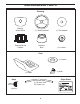
OPERATION These symbols may appear on your tractor or in literature supplied with the product. Learn and understand their meaning.
OPERATION KNOW YOUR TRACTOR READ THIS OWNER'S MANUAL AND SAFETY RULES BEFORE OPERATING YOUR TRACTOR Compare the illustrations with your tractor to familiarize yourself with the locations of various controls and adjustments. Save this manual for future reference.
OPERATION The operation of any tractor can result in foreign objects thrown into the eyes, which can result in severe eye damage. Always wear safety glasses or eye shields while operating your tractor or performing any adjustments or repairs. We recommend a wide vision safety mask over spectacles or standard safety glasses. HOW TO USE YOUR TRACTOR IMPORTANT: LEAVING THE IGNITION SWITCH IN ANY POSITION OTHER THAN "STOP" WILL CAUSE THE BATTERY TO BE DISCHARGED, (DEAD). TO SET PARKING BRAKE (See Fig.
OPERATION TO ADJUST GAUGE WHEELS (See Fig. 11) TO STOP MOWER BLADES (See Fig. 13) Gauge wheels are properly adjusted when they are slightly off the ground when mower is at the desired cutting height in operating position. Gauge wheels then keep the deck in proper position to help prevent scalping in most terrain conditions. NOTE:Adjust gauge wheels with tractor on a flat level surface. • Adjust mower to desired cutting height (See “TO ADJUST MOWER CUTTING HEIGHT” in the Operation section of this manual).
OPERATION BEFORE STARTING THE ENGINE TO TRANSPORT (See Fig. 14) When pushing or towing your tractor, be sure to disengage transmission by placing freewheel control in freewheeling position. Free wheel control is located under the seat. • Raise attachment lift to highest position with attachment lift control. • Raise seat and pull freewheel control up and back into the slot and release so it is held in the disengaged position. • Do not push or tow tractor at more than two (2) MPH.
OPERATION TO START ENGINE (See Fig. 9) PURGE TRANSMISSION When starting the engine for the first time or if the engine has run out of fuel, it will take extra cranking time to move fuel from the tank to the engine. • Be sure freewheel control is in the transmission engaged position. • Sit on seat in operating position, depress clutch/brake pedal and set parking brake. • Place motion control lever in neutral (N) position. • Move attachment clutch to “DISENGAGED” position.
OPERATION TO DUMP BAGGER (See Fig. 15) MULCHER PLUG 02331 Your tractor is equipped with a Dump Bag Alarm. To turn off the alarm disengage the attachment clutch switch. • Position tractor in location you wish to dump bagger. • Place motion control lever in Neutral position and set parking brake. • Raise dump handle to its highest position. Pull handle forward to raise bagger and dump clippings. • To continue mowing, be sure bagger is down and in proper operating position which will allow mower to operate.
OPERATION MOWING TIPS • • • • • • Mower should be properly leveled for best mowing performance. See “TO LEVEL MOWER HOUSING” in the Service and Adjustments section of this manual. The left hand side of mower should be used for trimming. If grass is extremely tall, it should be mowed twice to reduce load and possible fire hazard from dried clippings. Make first cut relatively high; the second to the desired height. Do not mow grass when it is wet. Wet grass will plug mower and leave undesirable clumps.
MAINTENANCE MAINTENANCE SCHEDULE BEFORE EACH USE EVERY 8 HOURS EVERY 25 HOURS EVERY 50 HOURS EVERY 100 HOURS EVERY SEASON BEFORE STORAGE Check Brake Operation Check Tire Pressure T Check Operator Presence & ROS Systems R A Check for Loose Fasteners C Check/Replace Mower Blades T Lubrication Chart 0 Check Battery Level R Clean Battery and Terminals 3 4 Check Transaxle Cooling Check Mower Levelness Check V-Belts Check Engine Oil Level Change Engine Oil (with oil filter) 1,2 Change Engine Oil (wi
MAINTENANCE TRACTOR BLADE CARE(See Figs.20-22) Always observe safety rules when performing any maintenance. For best results mower blades must be kept sharp. Replace bent or damaged blades. BRAKE OPERATION If tractor requires more than five (5) feet to stop at highest speed in highest gear on a level, dry concrete or paved surface, then brake must be checked and adjusted. (See “TO ADJUST BRAKE” in the Service and Adjustments section of this manual).
MAINTENANCE V-BELTS 6 STAR PATTERN BLADE Check V-belts for deterioration and wear after 100 hours of operation and replace if necessary. The belts are not adjustable. Replace belts if they begin to slip from wear. The center of this blade has a 6 star pattern. The bolt attaching this blade has Left Hand threads that loosens by turning ( ) clockwise and tighten by turning ( ) counterclockwise. TRANSAXLE COOLING The transmission fan and cooling fins should be kept clean to assure proper cooling.
MAINTENANCE TO CHANGE ENGINE OIL (See Fig. 23) AIR FILTER Determine temperature range expected before oil change. All oil must meet API service classification SG-SL. • Be sure tractor is on level surface. • Oil will drain more freely when warm. • Catch oil in a suitable container. • Remove oil fill cap/dipstick. Be careful not to allow dirt to enter the engine when changing oil. • Remove yellow cap from bottom fitting of drain valve and install the drain tube onto the fitting.
SERVICE AND ADJUSTMENTS WARNING: TO AVOID SERIOUS INJURY, BEFORE PERFORMING ANY SERVICE OR ADJUSTMENTS: • Depress clutch/brake pedal fully and set parking brake. • Place motion control lever in neutral (N) position. • Place attachment clutch in “DISENGAGED” position. • Turn ignition key to “STOP” and remove key. • Make sure the blades and all moving parts have completely stopped. • Disconnect spark plug wire from spark plug and place wire where it cannot come in contact with plug.
SERVICE AND ADJUSTMENTS TO LEVEL MOWER HOUSING • Adjust the mower while tractor is parked on level ground or driveway. Make sure tires are properly inflated (See “PRODUCT SPECIFICATIONS” section of this manual). If tires are over or underinflated, you will not properly adjust your mower. • • SIDE-TO-SIDE ADJUSTMENT (See Figs. 26 and 27) • Raise mower to its highest position. • At the midpoint of both sides of mower, measure height from bottom edge of mower to ground.
SERVICE AND ADJUSTMENTS TO REPLACE MOWER BLADE DRIVE BELT (See Fig. 30) TO REPLACE MOTION DRIVE BELT (See Fig. 31) Park the tractor on level surface. Engage parking brake. Park the tractor on level surface. Engage parking brake. For assistance, there is a belt installation guide decal on bottom side of left footrest. BELT REMOVAL • Remove mower from tractor (See “TO REMOVE MOWER” in this section of this manual). • Remove screws from RH mandrel cover and remove cover.
SERVICE AND ADJUSTMENTS TRANSAXLE MOTION CONTROL LEVER NEUTRAL ADJUSTMENT (See Fig. 32) RETAINING RING The motion control lever has been preset at the factory and adjustment should not be necessary. • Loosen adjustment bolt in front of the right rear wheel, and lightly tighten. • Start engine and move motion control lever until tractor does not move forward or backward. • Hold motion control lever in that position and turn engine off.
SERVICE AND ADJUSTMENTS REPLACING BATTERY (See Fig. 35) TO REMOVE HOOD AND GRILL ASSEMBLY (See Fig. 36) WARNING: Do not short battery terminals by allowing a wrench or any other object to contact both terminals at the same time. Before connecting battery, remove metal bracelets, wristwatch bands, rings, etc. Positive terminal must be connected first to prevent sparking from accidental grounding. • • • • • • • • • • Open battery cover.
STORAGE ENGINE Immediately prepare your tractor for storage at the end of the season or if the tractor will not be used for 30 days or more. FUEL SYSTEM IMPORTANT: IT IS IMPORTANT TO PREVENT GUM DEPOSITS FROM FORMING IN ESSENTIAL FUEL SYSTEM PARTS SUCH AS CARBURETOR, FUEL FILTER, FUEL HOSE, OR TANK DURING STORAGE. ALSO, EXPERIENCE INDICATES THAT ALCOHOL BLENDED FUELS (CALLED GASOHOL OR USING ETHANOL OR METHANOL) CAN ATTRACT MOISTURE WHICH LEADS TO SEPARATION AND FORMATION OF ACIDS DURING STORAGE.
TROUBLESHOOTING POINTS PROBLEM CAUSE CORRECTION Will not start 1. 2. 3. 4. 5. 6. 7. Out of fuel. Engine not “CHOKED” properly. Engine flooded. Bad spark plug. Dirty air filter. Dirty fuel filter. Water in fuel. 1. 2. 3. 4. 5. 6. 7. 8. 9. Loose or damaged wiring. Carburetor out of adjustment. 8. 9. 10. Engine valves out of adjustment. 10. Fill fuel tank. See “TO START ENGINE” in Operation section. Wait several minutes before attempting to start. Replace spark plug. Clean/replace air filter.
TROUBLESHOOTING POINTS PROBLEM CAUSE CORRECTION Engine continues to run when operator leaves seat with attachment clutch engaged 1. Faulty operator-safety presence control system. 1. Check wiring, switches and connections. If not corrected, contact an authorized service center/ department. Poor cut - uneven 1. 2. 3. 4. 5. Worn, bent or loose blade. Mower deck not level. Buildup of grass, leaves, and trash under mower. Bent blade mandrel.
SERVICE NOTES 30
SUGGESTED GUIDE FOR SIGHTING SLOPES FOR SAFE OPERATION FOL DA L O NG D THIS OT IS T A E D 15 D LINE EGR E E SLO PE ONLY RIDE UP AND DOWN HILL, NOT ACROSS HILL 15 DEGREES MAX. WARNING: To avoid serious injury, operate your tractor up and down the face of slopes, never across the face. Do not mow slopes greater than 15 degrees. Make turns gradually to prevent tipping or loss of control. Exercise extreme caution when changing direction on slopes. 1. Fold this page along dotted line indicated above. 2.
Jonsered Motor AB, S-433 81 Partille, Sweden. 532 41 02-74 Rev. 4 05.12.09 SR Printed in the U.S.A.