Operator’s manual (EPA) Please read the operator’s manual carefully and make sure you understand the instructions before using the machine.
KEY TO SYMBOLS Symbols Switch off the engine by moving the stop switch to the STOP position before carrying out any checks or maintenance. WARNING! Clearing saws, brushcutters and trimmers can be dangerous! Careless or incorrect use can result in serious or fatal injury to the operator or others. It is extremely important that you read and understand the contents of the operator’s manual. Always wear approved protective gloves. Regular cleaning is required.
CONTENTS Contents KEY TO SYMBOLS Symbols ....................................................................... CONTENTS Contents ...................................................................... Note the following before starting: ................................ INTRODUCTION Dear customer! ............................................................ WHAT IS WHAT? What is what on the clearing saw? (GR41/GR50/RS44) WHAT IS WHAT? What is what on the clearing saw? (RS52) ..................
INTRODUCTION Dear customer! Congratulations on your choice to buy a Jonsered product! Your purchase gives you access to professional help with repairs and service whenever this may be necessary. If the retailer who sells your machine is not one of our authorized dealers, ask for the address of your nearest servicing dealer. It is our wish that you will be satisfied with your product and that it will be your companion for a long time. Think of this operator′s manual as a valuable document.
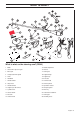
WHAT IS WHAT? 23 24 What is what on the clearing saw? (RS44) 1 Blade 15 Handle adjustment 2 Grease filler cap, bevel gear 16 Harness 3 Bevel gear 17 Locking nut 4 Cutting attachment guard 18 Support flange 5 Shaft 19 Support cup 6 Handlebar 20 Drive disc 7 Throttle control 21 Trimmer head 8 Stop switch 22 Socket spanner 9 Throttle lockout 23 Operator’s manual 10 Support eyes for harness 24 Transport guard 11 Cylinder cover 25 Allen key 12 Starter handle 26 Carburettor scre
WHAT IS WHAT? What is what on the clearing saw? (RS52) 1 Blade 15 Fuel tank 2 Grease filler cap, bevel gear 16 Socket spanner 3 Bevel gear 17 Handle adjustment 4 Cutting attachment guard 18 Locking nut 5 Shaft 19 Support flange 6 Handlebar 20 Drive disc 7 Throttle control 21 Transport guard 8 Stop switch 22 Harness 9 Throttle lockout 23 Operator’s manual 10 Support eyes for harness 24 Allen key 11 Cylinder cover 25 Locking pin 12 Starter handle 26 Gearbox grease 13 Choke co
GENERAL SAFETY PRECAUTIONS Important IMPORTANT! The machine is only designed for trimming grass, grass clearing and/or forestry clearing. The only accessories you can operate with this engine unit are the cutting attachments we recommend in the chapter on Technical data. ! WARNING! Listen out for warning signals or shouts when you are wearing hearing protection. Always remove your hearing protection as soon as the engine stops.
GENERAL SAFETY PRECAUTIONS Machine′s safety equipment Press the throttle lockout and make sure it returns to its original position when you release it. This section describes the machine′s safety equipment, its purpose, and how checks and maintenance should be carried out to ensure that it operates correctly. See the ”What is what?” section to locate where this equipment is positioned on your machine.
GENERAL SAFETY PRECAUTIONS Cutting attachment guard This guard is intended to prevent loose objects from being thrown towards the operator. The guard also protects the operator from accidental contact with the cutting attachment. Check that the guard is undamaged and not cracked. Replace the guard if it has been exposed to impact or is cracked. Always use the recommended guard for the cutting attachment you are using. See chapter on Technical data.
GENERAL SAFETY PRECAUTIONS For mufflers it is very important that you follow the instructions on checking, maintaining and servicing your machine. See instructions under the heading Checking, maintaining and servicing the machine’s safety equipment. Never use a machine that has a faulty muffler. Regularly check that the muffler is securely attached to the machine. If the muffler on your machine is fitted with a spark arrestor screen this must be cleaned regularly.
GENERAL SAFETY PRECAUTIONS Cutting equipment General rules This section describes how to choose and maintain your cutting equipment in order to: • Reduce the risk of blade thrust. • Obtain maximum cutting performance. • Extend the life of cutting equipment. Only use cutting attachments with the guards we recommend! See the chapter on Technical data. IMPORTANT! Only use cutting attachments with the guards we recommend! See the chapter on Technical data.
GENERAL SAFETY PRECAUTIONS Sharpening grass cutters and grass blades • See the cutting attachment packaging for correct sharpening instructions. Sharpen blades and cutters using a single-cut flat file. • Sharpen all edges equally to maintain the balance of the blade. ! WARNING! Always discard a blade that is bent, twisted, cracked, broken or damaged in any other way. Never attempt to straighten a twisted blade so that it can be reused. Only use original blades of the specified type.
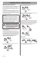
ASSEMBLY Assembling the handlebar and throttle • Unscrew the knob from the handlebar mounting. • Position the handlebar as shown. Fit the mounting components and tighten the knob lightly. • Fit the right handle to the handlebar using the screw, washer, sleeve and nut as shown. Tighten.
ASSEMBLY • Fit the support flange (F) on the output shaft. Make sure that the blade is centered by fitting it to the guide on the support flange. • Screw the support cup (E) onto the output shaft threads (CAUTION! Left-hand thread). Tighten to a torque of 3550 Nm (3.5-5.0 kpm). Use the socket spanner in the tool kit. Note that the locking pin (C) must remain inside the gear housing to lock the drive disk. Hold the shaft of the socket spanner as close to the blade guard/combination guard as possible.
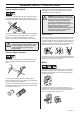
ASSEMBLY • Tighten the trimmer head to a torque of 35-50 Nm (3.5-5 kpm). Standard harness H Safety release At the front is an easily accessible, quick release. Use this if the engine catches fire or in any other emergency situation that requires you to free yourself from the machine and harness. • To dismantle, follow the instructions in the reverse order.
ASSEMBLY Vector harness 6 The elastic strap (B) can be tightened to transfer more load from the shoulder straps to the hip strap. Safety release Push down the red release lever to release the machine from the harness. Correct balance 1 The machine is balanced by moving the suspension ring on the machine forwards or backwards. On some models the suspension ring is fixed, however, this will then have a number of holes for the support hook.
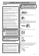
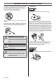
FUEL HANDLING Fuel safety Gasoline Never start the machine: 1 If you have spilled fuel on it. Wipe off the spillage and allow remaining fuel to evaporate. 2 If you have spilled fuel on yourself or your clothes, change your clothes. Wash any part of your body that has come in contact with fuel. Use soap and water. 3 If the machine is leaking fuel. Check regularly for leaks from the fuel cap and fuel lines.
FUEL HANDLING Fueling Mixing • Always mix the gasoline and oil in a clean container intended for fuel. • Always start by filling half the amount of the gasoline to be used. Then add the entire amount of oil. Mix (shake) the fuel mixture. Add the remaining amount of gasoline. • ! Mix (shake) the fuel mixture thoroughly before filling the machine’s fuel tank. WARNING! Taking the following precautions, will lessen the risk of fire: Do not smoke or place hot objects near fuel.
STARTING AND STOPPING Check before starting • Check the blade to ensure that no cracks have formed at the bottom of the teeth or by the centre hole. The most common reason why cracks are formed is that sharp corners have been formed at the bottom of the teeth while sharpening or that the blade has been used with dull teeth. Discard a blade if cracks are found.
STARTING AND STOPPING Starting ! WARNING! When the engine is started with the choke in either the choke or start throttle positions the cutting attachment will start to rotate immediately. Hold the body of the machine on the ground using your left hand (CAUTION! Not with your foot!). Grip the starter handle, slowly pull out the cord with your right hand until you feel some resistance (the starter pawls grip), now quickly and powerfully pull the cord.
WORKING TECHNIQUES General working instructions 6 Keep a good balance and a firm foothold. 7 Always hold the machine with both hands. Hold the machine on the right side of your body. IMPORTANT! This section describes the basic safety precautions for working with clearing saws and trimmers. If you encounter a situation where you are uncertain how to proceed you should ask an expert. Contact your dealer or your service workshop. Avoid all usage which you consider to be beyond your capability.
WORKING TECHNIQUES ! WARNING! Sometimes branches or grass get caught between the guard and cutting attachment. Always stop the engine before cleaning. • You should plan the strip so that you avoid going over ditches or other obstacles on the ground. You should also orient the strip to take advantage of wind conditions, so that cleared stems fall in the cleared area of the stand.
WORKING TECHNIQUES • To fell a tree forwards, the bottom of the tree should be pulled backwards. Pull the blade backwards with a quick, firm movement. • Large stems must be cut from two sides. First determine which direction the stem will fall. Make the first cut on the felling side. Then finish cutting the stem from the other side. Adjust the cutting pressure to match the size of the stem and the hardness of the wood. Small stems require more pressure, while large stems require less pressure.
WORKING TECHNIQUES Grass trimming with a trimmer head Sweeping • The fan effect of the rotating cord can be used for quick and easy clearing up. Hold the cord parallel to and above the area to be swept and move the tool to and fro. • When cutting and sweeping you should use full throttle to obtain the best results. Trimming • Hold the trimmer head just above the ground at an angle. It is the end of the cord that does the work. Let the cord work at its own pace.
MAINTENANCE Carburetor • Your Jonsered product has been designed and manufactured to specifications that reduce harmful exhaust fumes. The engine will be run in after it has used 8-10 tanks of fuel. To ensure that the engine runs at peak performance and produces as little harmful exhaust fumes as possible after the running-in period, ask your dealer/service workshop (which has a rev counter for this purpose) to adjust your carburettor.
MAINTENANCE Low speed jet L High speed jet H (RS52) Try to find the highest idling speed, turning the low speed needle L clockwise respectively counter-clockwise. When the highest speed has been found, turn the low speed needle L 1/ 4 turn counter-clockwise. The high speed jet H affects the engine power, speed, temperature and fuel consumption. If the high speed jet H is set too lean (screwed in too far) the engine speed will be too high and cause engine damage.
MAINTENANCE Correctly adjusted carburetor Cooling system When the carburetor is correctly adjusted the machine will accelerate without hesitation and burble a little at maximum speed. It is also important that the cutting attachment does not rotate at idle. If the low speed jet L is set too lean it may cause starting difficulties and poor acceleration. If the high speed jet H is set too lean it will result in less power, less performance, poor acceleration and/or damage to the engine.
MAINTENANCE Bevel gear The bevel gear is filled with the right amount of grease at the factory. However, before using the machine you should check that the bevel gear is filled 3/4 full with grease. Use JONSERED special grease. The grease in the bevel gear does not normally need to be changed except if repairs are carried out. Spark plug The spark plug condition is influenced by: • Incorrect carburetor adjustment. • An incorrect fuel mixture (too much or incorrect type of oil). • A dirty air filter.
MAINTENANCE Maintenance schedule The following is a list of the maintenance that must be performed on the machine. Most of the items are described in the Maintenance section. The user must only carry out the maintenance and service work described in this manual. More extensive work must be carried out by an authorised service workshop. Maintenance Daily maintenance Clean the outside of the machine. X Check that the harness is not damaged.
TECHNICAL DATA Technical data Technical data RS44 RS52 Cylinder displacement, cu.in/cm3 2,70/44,3 3,10/50,8 Cylinder bore, inch/mm 1,65/42 1,77/45 Stroke, inch/mm 1,26/32 1,26/32 Idle speed, rpm 2700 2700 Recommended max. speed, rpm 13500 13500 Speed of output shaft, rpm 10500 10500 Max. engine output, acc.
FEDERAL EMISSION CONTROL WARRANTY STATEMENT YOUR WARRANTY RIGHTS AND OBLIGATIONS rights and responsibilities, you should contact your nearest authorized servicing dealer or call Jonsered, at Sweden +4636-146500. The EPA (The US Environmental Protection Agency), Environment Canada and Jonsered are pleased to explain the emissions control system warranty on your 2001 and later small nonroad engine. In U.S.
Trimmy SII 1 2,4-3,3 mm .095"-.
Auto 55 1 2 3 >1,1 Kw 1.) <1,1 Kw 2.) 2,7-3,3 mm .106-.
1150269-95 ´®z+R:•¶5Q¨ ´®z+R:•¶5Q¨ 2006-08-23