
Assembly and Installation Instructions

Turn on the power at fuse or circuit box
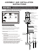
Ball Nut (G)
Mounting Strap (A)
Green Grounding
Screw (E)
Fixture Mounting
Screw(D)
Mounting Screw (B)
Wire Nut (C)
Lock Nut (F)
The following parts are available for re-order if damaged or missing.
Spare Parts List:
A: 24"
B: 23-1/4"~65-1/4"
A
B
5. Pull out the source wires from the outlet box. Make wire
connections using wire nuts as follows:
---Connect the smooth-coated wire (marked) from the fixture to
the black wire from the power source.
---Connect the ribbed-coated wire (unmarked) from the fixture to
the white wire from the power source.
---Attach the fixture grounding wire to the mounting strap with
the green grounding screw, and then connect it to the
house grounding wire with a wire nut.
Carefully put the wires back into the outlet box.
6. Attach the fixture canopy to the mounting strap by inserting the
fixture mounting screws, and then secure it with two ball nuts.
7. Install bulbs (not included). Check relamping label at socket
area or packaging for maximum allowed wattage.
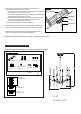
8.Angled mounting recommended for a vaulted or angled ceiling. (See Fig. 1)
Fig. 1
Outlet Box
Support Brace
Canopy
Coupling Kit
Mounting Hardware
(1 SET)
12”L Rods
w/threaded pipe
6”L Rod
w/threaded pipe
3”L Rod
w/threaded pipe