
Installation Manual Part 2
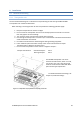
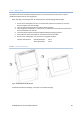
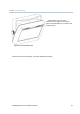
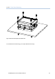
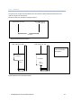
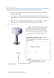
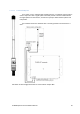
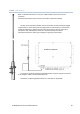
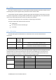
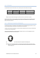
Table Of Contents
- 8 Installation
- 8.1 Mechanical Mounting
- 8.2 Cabling
- 8.3 Wiring and Connections
- 8.3.1 Transponder
- 8.3.1.1 Pictorial display of typical connections to the transponder
- 8.3.1.2 Label in transponder with connection tables
- 8.3.1.3 Power connection
- 8.3.1.4 Sensor connections
- 8.3.1.5 External display – ECDIS/Radar connections
- 8.3.1.6 Pilot / Aux. Display connection
- 8.3.1.7 Alarm Connection
- 8.3.1.8 Detailed description of connections, fuses, factory reset etc.
- 8.3.2 Display Unit:
- 8.3.1 Transponder
- 9 Initial configuration
- 10 Operation Instructions

TR-8000 Operator and Installation Manual 48
8.2.2 VHF antenna
The table below shows the attenuation on the VHF frequencies with different cable types:
Cable Type
Attenuation @150
MHz (dB/100m)
Diameter (mm)
Weight (kg/100m)
RG214
7
10,8
18,5
RG225
8
10,9
23,3
Example: A RG 214 cable with length of 40 meters will have an attenuation of 2,8 dB.
Please keep the cables as short as possible, and be aware that 3 dB losses mean only half the output
power. If you have a transmitter delivering 12,5 W, and you have 3 dB losses in the cable, only 6,25
Watts will be at the antenna.
8.2.3 Cable between Transponder and Display Unit
The cable connecting the Transponder and the Display Unit has specially designed connectors on each
end for waterproofing. The cable itself is a standard CAT-5 network cable
In order to ease wiring and installation, an optional cable is available with one end open, delivered with
a small kit for post wiring assembly.
If the specified cable type is not used, the splash proofing of the unit is seriously degraded and the
warranty is void if used in humid environment.
Figure 8-7 Connection cable for interconnection between the Transponder and the Display Unit
NOTE! If the units are mounted indoors in a warm dry environment without any need for water
tightness, a standard CAT-5 or CAT-6 network cable may be used between the Transponder
and the Display unit