Jøtul F 105 R Jøtul F 105 Manual Version P02 NL - Installatie- en montagehandleiding DE/CH - Montage- und Gebrauchsanleitung für Deutschland, Schweiz und Österreich 3 27 CH - Manuel d’installation et d’utilisation 51 CH - Manuale di installazione ed uso 75 Jøtul F 105 B Jøtul F 105 LL Jøtul F 105 SL Registrieren Sie das Produkt im Internet innerhalb von drei Monaten nach dem Kauf. 10 Jahre Garantie auf Außen-Gussteile bei Registrierung - jotul.
NEDERLANDS Inhoudsopgave 1.0 Technische gegevens ................................ 3 2.0 Wettelijke voorschriften ............................. 3 3.0 Veiligheid ................................................... 4 4.0 Installatie ................................................. 12 5.0 Dagelijks gebruik ..................................... 20 6.0 Onderhoud .............................................. 21 7.0 Groot onderhoud ..................................... 21 8.0 Optionele extra’s ....
NEDERLANDS 3.0 Veiligheid 3.2 Vloer NB! Om optimale prestaties en veiligheid te garanderen, raadt Jøtul aan haar kachels te laten monteren door een gekwalificeerd installateur (zie www.jotul.com voor een volledige dealerlijst). Fundering Aanpassingen aan het product door de distributeur, installateur of consument kunnen ertoe leiden dat het product en de beveiligingen niet naar behoren functioneren. Hetzelfde geldt voor de installatie van niet door Jøtul geleverde accessoires of optionele extra’s.
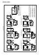
Fig 1 Jøtul F 105 B (basis) Jøtul F 105 R B (basis) Convectieplaat + = Jøtul F 105 LL (Lange poten) Jøtul F 105 R LL (Lange poten) Convectieplaat + = Jøtul F 105 SL (Korte poten) Jøtul F 105 R SL (Korte poten) Convectieplaat = + 5
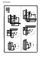
290 325 410 luchtaansluiting * Externe Jøtul F 105 R met lange poten en spekstenen bovenkant 410 410 Jøtul F 105 R met basis en spekstenen bovenkant 410 Jøtul F 105 R met basis 600 Jøtul F 105 R met lange poten 690 740 690 740 325 590 125 590 125 590 *40 590 *40 290 325 290 325 *80 125 *80 125 550 Jøtul F 105 R Y Minimale afmetingen voor de vloerplaat X/Y = In overeenstemming met nationale weten regelgeving. ** Minimale afstand tot brandbare materialen.
Externe luchtaansluiting midden Kachelpijp midden 605 400 Jøtul F 105 R Minimale afstand tot brandbare muur 510 631 * Externe luchtaansluiting *** Afstand tot brandbare muur met halfgeïsoleerde/afgeschermde kachelpijp (isolatie min.30 mm) *40 Externe luchtaansluiting midden * 216 385 *603 Kachelpijp midden * 76 (korte bein) *40 430 Afb.
*40 350 1072 * Externe luchtaansluiting 350 Geïntegreerd 720 656 175 Extern *40 856 *348 376 376 *348 225 430 790 Jøtul F 105 R Minimale afstand tot brandbare muur beschermd door brandmuur 350 1050 317 225 430 225 350 867 175 8 966 500 Afb.
290 410 luchtaansluiting * Externe Jøtul F 105 met lange poten en spekstenen bovenkant 410 590 150 690 350 325 740 350 325 *80 410 Jøtul F 105 met basis en spekstenen bovenkant 410 350 Jøtul F 105 met basis 550 Jøtul F 105 150 325 600 Jøtul F 105 met lange poten 350 590 150 690 350 740 290 325 290 325 590 *40 590 *40 x Vloerplaat Minimale afmetingen voor de vloerplaat X/Y = In overeenstemming met nationale weten regelgeving. ** Minimale afstand tot brandbare materialen.
Externe luchtaansluiting midden Kachelpijp midden Med standard konveksjonsplate 605 400 Jøtul F 105 Minimale afstand tot brandbare muur 350 ***250 527 * Externe luchtaansluiting *** Afstand tot brandbare muur met halfgeïsoleerde/afgeschermde kachelpijp (isolatie min.30 mm) *40 Externe luchtaansluiting midden * 216 200 ***100 *499 Kachelpijp midden * 76 (korte bein) * 40 10 300 Afb.
92 75 75 225 327 *299 856 *299 327 355 150 895 *40 225 * Externe luchtaansluiting *40 Geïntegreerd 774 656 225 Extern 742 150 355 75 951 470 Jøtul F 105 Minimale afstand tot brandbare muur beschermd door brandmuur Brandmuur Brandbare muur 900181-P01 75 264 688 225 100 Afb.
NEDERLANDS Toevoer van frisse lucht Afb. 2C, via de vloer en kelder De lucht die gebruikt wordt voor verbranding in een goed geïsoleerd huis moet worden ververst. Dit is met name van belang voor huizen met mechanische ventilatie. Deze luchtverversing kan op een aantal manieren worden bereikt. Het belangrijkste is dat er lucht wordt aangevoerd naar de ruimte waar de kachel geplaatst is.
NEDERLANDS Afb. 4 4.0 Installatie NB: Controleer voordat u met de installatie begint of de haard onbeschadigd is. NB: Het product is zwaar! Zorg voor hulp bij het plaatsen en installeren. De verbrandingskamer is zwaar. Zorg dat het product niet kantelt. NB: Zet niets op de bovenplaat van de kachel, aangezien dit de verf/het email permanent kan beschadigen. NB: Lees de installatie- en bedieningsinstructies aandachtig door voordat u de haard plaatst! 4.
NEDERLANDS 4.2 Voorbereidingen voor de Jøtul F 105 SL met korte poten Afb. 7 De Jøtul F 105 SL (met korte poten) kan uitsluitend geïnstalleerd worden op vloeren met een ondergrond en structuur van onbrandbaar materiaal. Dit geldt ook als het product op een vloerplaat geplaatst wordt. Let op! Het onbrandbare gebied moet zich ten minste tot 500 mm voor de kachel uitstrekken. Let op! Wij raden het gebruik van vloerverwarming (met water of elektrisch) in dit gebied af. Afb. 6 A A A A 5.
NEDERLANDS Afb. 10 4.3 Voorbereidingen voor de Jøtul F 105 met basis Afb. 9 B 1 A A 2 A A C D 4. Til de kachel van de pallet. 5. Zet de kachel neer en stel de horizontale positie met behulp van de 4 stelschroeven af. Gebruik de zeskantsleutel in de zak met schroeven. Teken de positie op de muur af als er gebruik wordt gemaakt van een achteruitlaat voor de kachelpijp en de externe luchttoevoer. 6. Let op! Houd rekening met de hoogte van de vloerplaat. Goedkeuringsetiket 3 Afb. 11 1.
NEDERLANDS Externe luchttoevoer door de vloer Externe luchttoevoer via een achteruitlaat Afb. 12 Afb. 14 A B B 1. Bevestig de adapter (A) aan de onderkant van de verbrandingskamer met behulp van de bijgeleverde schroeven (B) (Vooraf gemonteerd Jøtul F 105 B). A B B 1. Bevestig de adapter (A) aan de verbrandingskamer met behulp van de twee bijgeleverde schroeven (B) (Vooraf gemonteerd Jøtul F 105 B). Afb. 13 Afb. 15 C B C B A A C B C 2.
NEDERLANDS Externe luchtaansluiting via de basis 4.4 Schoorsteen en kachelpijp Via een achteruitlaat • Afb. 16 • • 100 • • • • • 3. Voor het bevestigen van een Ø 80 inlaatkanaal voor frisse lucht (optionele uitrusting – artikelnr. 51047509), zie de handleiding (artikelnr. 10047508) bij de externe luchtaansluiting. Sluit de slang met een slangklem op de externe luchtaansluiting aan. De isolatie van de externe luchtslang eindigt ongeveer 100 mm onder de verbrandingskamer.
NEDERLANDS 4.5 Een kachelpijp met een bovenuitlaat verbinden 4.6 Een kachelpijp met een achteruitlaat verbinden Het product wordt door de fabriek geleverd met een rookuitlaat als bovenuitlaat. Het product wordt door de fabriek geleverd met een rookuitlaat als bovenuitlaat. Als u een achteruitlaat wilt, gaat u als volgt te werk: Afb. 18 Afb. 19 A B A 1. Leid de kachelpijp (A) door de bovenplaat en plaats deze vervolgens in de bovenste rookuitlaat. 2. Goed afdichten met een pakking (B). 1.
NEDERLANDS Afb. 21 Afb. 23 D B C B D A C A 3. Draai de schroeven los (A) en verwijder de rookuitlaat (B) uit de bovenuitlaat. 5. Bevestig de rookuitlaat (A) aan de achteruitlaat met de twee schroeven (C) via de binnenkant van de verbrandingskamer. 6. Bevestig de kap (B) aan de bovenuitlaat met de twee schroeven (D) via de binnenkant van de verbrandingskamer. 7. Plaats de uitlaatplaat terug. 8. Plaats de keerplaat. Afb. 22 B Afb. 24 B A A B 4.
NEDERLANDS Afb. 25 4.6 Prestatiecontrole Als het product is gemonteerd, moet u altijd de bedieningshendel controleren. Deze behoort makkelijk te bewegen en goed te werken. Afb. 27 C B 10. Breng de kachelpijp aan in de achteruitlaat. Let op: Het is belangrijk dat de verbindingen/kachelpijpen volledig zijn afgedicht. Het ontsnappen van lucht kan tot gevolg hebben, dat ze niet naar behoren functioneren.
NEDERLANDS 5.0 Dagelijks gebruik Geur bij eerste gebruik van de haard Als de haard voor de eerste keer wordt gebruikt, kan irriterend gas vrijkomen dat onaangenaam kan ruiken. Dit gebeurt omdat de verf opdroogt. Het gas is niet giftig, maar toch is het beter om de ruimte goed te ventileren. Stook het vuur flink op totdat alle sporen van gas zijn verdwenen en geen rook of geuren meer zijn waar te nemen. Eerste keer stoken Open de luchtopening (Afb. 27) volledig uit te trekken.
NEDERLANDS 5.2 As verwijderen 6.4 Inspectie van de haard De Jøtul F 105 heeft een aslade waarmee het eenvoudig is om as te verwijderen. • Verwijder de as niet voordat de haard koud is. • Schraap het as over het rooster op de bodem, zodat het as in de aslade valt. Gebruik een handschoen of iets dergelijks om uw hand te beschermen. Pak de hendel van de aslade vast en haal de aslade eruit. Zorg ervoor dat de aslade nooit zo vol is dat er geen as meer door het rooster in de aslade kan vallen.
NEDERLANDS 3. Uitlaatplaat: Til de voorrand van de uitlaatplaat (B) omhoog en omlaag en draai deze uit de verbrandingskamer. 4. Til het asrooster (D) in de middelste stand aan de voorkant op en til vervolgens de aslade uit de verbrandingskamer. 5. Verwijder de drie schroeven waarmee de brandplaat. Til een van de kanten van de brandplaat omhoog en draai deze uit de verbrandingskamer. Afb. 31 A 7.2 Glas en pakking in de deur vervangen Afb. 30 A A A A 1.
NEDERLANDS Afb. 32 Afb. 34 B A 1. Verwijder de pakking (A) die op de binnenkant van de deur zit, maak de groef van de pakking schoon en lijm er een nieuwe pakking op. A 4. Verwijder het glas (A) voorzichtig. Verwijder de pakkingen (B) en (C) en maak de groeven van de pakkingen schoon. 5. Lijm er nieuwe pakkingen op. Afb. 33 B Afb. 35 A A A 2. Als u een glaspakking of glas moet vervangen, verwijdert u eerst de deurhendel (zie 2-4). 3. Schroef de glashouder (B) los die met 4 schroeven (A) vastzit.
NEDERLANDS 8.0 Optionele extra’s 8.1 Externe luchtaansluiting Externe luchtaansluiting, Ø 80 mm - Cat. nr. 51047509 8.2. Set spekstenen bovenkant Cat. nr. 51049066 8.3 Asrand voor poten BP - cat. nr. 51049066 WHE - cat. nr. 51049516 8.4 Hendel aslade Cat. nr. 51049070 10.0 Garantievoorwaarden Jøtul maakt al sinds 1853 kwalitatief hoogwaardige kachels en haarden met een lange levensduur. We zijn zo zeker van onze kwaliteit dat we onze klanten een verlengde garantie geven, zonder extra kosten.
NEDERLANDS Voor pelletkachels, glas, steen, beton, email en lak (waaronder begrepen maar niet beperkt tot breuken, scheuren, barsten, blaasjes, verkleuring of craquelé) geldt de nationale wetgeving die van toepassing is op de verkoop van consumentengoederen. Deze garantie is geldig voor aankopen gedaan binnen de Europese Economische Ruimte.
DEUTSCH Inhalt 1.0 Behördliche Auflagen • 1.0 Technische Daten ....................................27 2.0 Behördliche Auflagen ..............................27 3.0 Sicherheit ................................................28 4.0 Installation ..............................................37 5.0 Tägliche Nutzung ....................................45 6.0 Pflege ......................................................46 • 7.0 Wartung ...................................................47 8.
DEUTSCH 3.0 Sicherheit 3.2 Boden Hinweis: Um maximale Leistung und Sicherheit zu gewährleisten, empfiehlt Jøtul, seine Kamine von ausgebildetem Fachpersonal installieren zu lassen. (Eine vollständige Händlerliste finden Sie unter www.jotul. com.). Fundament Jegliche Veränderungen am Produkt, die durch einen Händler, Installateur oder Kunden vorgenommen werden, können dazu führen, dass das Produkt oder seine Sicherheitsfunktionen nicht wie vorgesehen arbeiten.
DEUTSCH Abb 1 Jøtul F 105 B (Sockel) Jøtul F 105 R B (Sockel) Konvektionsplatte + = Jøtul F 105 LL (Lange Beine) Jøtul F 105 R LL (Lange Beine) Konvektionsplatte + = Jøtul F 105 SL (Kurze Beine) Jøtul F 105 R SL (Kurze Beine) Konvektionsplatte = + 29
290 325 410 Jøtul F 105 R mit langen Beinen und Specksteinaufsatz 410 * Außenluftanschluss 410 Jøtul F 105 R mit Sockel und Specksteinaufsatz 410 Jøtul F 105 R mit Sockel 600 Jøtul F 105 R mit langen Beinen 690 740 690 740 325 590 125 590 125 590 *40 590 *40 290 325 290 325 *80 125 *80 125 550 Jøtul F 105 R Minimale Abmessungen der Fußbodenplatte / X/Y = Gemäß den geltenden nationalen Gesetzen und Regelungen ** Min. Abstand zu Möbeln / brennbare Materialien.
Außenluftanschlussmitte Rauchgasrohrmitte * Außenluftanschluss *** Abstand zu brennbarer Wand mit halbisoliertem/geschütztem Rauchgasrohr (mind. 30 mm Isolierung) *40 Außenluftanschlussmitte 510 631 605 400 Jøtul F 105 R Min. Abstand zu brennbarer Wand 385 *603 Rauchgasrohrmitte * 216 * 76 (kurze Beine) *40 430 Abb.
350 Integriert *40 1072 * Außenluftanschluss 720 656 175 Ekstern *40 350 856 *348 376 376 *348 225 430 790 Jøtul F 105 R Min. Abstand zu brennbarer Wand die von Feuerschutzwand geschutzt ist 350 1050 225 430 225 317 350 867 175 32 966 500 Abb.
290 410 Jøtul F 105 mit langen Beinen und Specksteinaufsatz 410 590 150 690 350 325 740 350 325 * Außenluftanschluss 590 410 Jøtul F 105 mit Sockel und Specksteinaufsatz 410 Jøtul F 105 550 350 Jøtul F 105 mit Sockel *80 150 x Fußbodenplatte Minimale Abmessungen der Fußbodenplatte / X/Y = Gemäß den geltenden nationalen Gesetzen und Regelungen ** Min. Abstand zu Möbeln / brennbare Materialien.
Senter uteluftstilslutning Rauchgasrohrmitte 350 ***250 527 605 * Außenluftanschluss *** Abstand zu brennbarer Wand mit halbisoliertem/geschütztem Rauchgasrohr (mind. 30 mm Isolierung) *40 Senter uteluftstilslutning 400 Jøtul F 105 Min. Abstand zu brennbarer Wand 200 ***100 *499 Rauchgasrohrmitte * 216 * 76 (kurze Beine) * 40 34 300 Abb.
*40 225 * Außenluftanschluss 1192 75 75 327 *299 856 *299 327 355 150 895 *40 225 Integriert 774 656 225 Ekstern 742 150 355 75 951 470 Jøtul F 105 Min. Abstand zu brennbarer Wand die von Feuerschutzwand geschutzt ist Feuerschutzwand Brennbare Wand 900181-P01 75 264 225 688 100 100 Abb.
DEUTSCH Frischluftzufuhr Abb. 2C, durch Fußboden und Fundament Die für eine Verbrennung benötigte Luft muss in jedem gut isolierten Haus ersetzt werden. Dies ist insbesondere in Häusern mit mechanischer Lüftung wichtig. Diese Ersatzluft lässt sich auf verschiedene Weise beschaffen. Dabei kommt es darauf an, die Luft in den Raum zu leiten, wo sich der Kaminofen befindet. Positionieren Sie daher die Außenwandventile so nahe wie möglich am Kaminofen.
DEUTSCH Abb. 4 4.0 Installation Hinweis: Vergewissern Sie sich vor Beginn der Installation, dass der Kamin unversehrt ist. Hinweis: Das Produkt ist schwer! Bei Positionierung und Installation benötigen Sie Hilfe. Stellen Sie sicher, dass das Produkt nicht umkippt. Hinweis: Stellen Sie nichts auf die Deckplatte des Kaminofens. Andernfalls können bleibende Schäden an Lack-/ Emailleoberflächen entstehen.
DEUTSCH 4.2 Vorbereitungen für Jøtul F 105 SL (mit kurzen Beinen) Abb. 7 Jøtul F 105 SL kann nur auf Böden installiert werden, deren Oberfläche und Struktur aus nicht brennbaren Materialien bestehen. Dies gilt ebenfalls, wenn das Produkt auf einer Fußbodenplatte ruht. Hinweis: Der nicht brennbare Bereich muss mindestens bis 500 mm vor den Kaminofen reichen. Hinweis: Wir raten davon ab, in diesem Bereich eine Fußbodenheizung (wasserbasiert oder elektrisch) zu installieren. Abb. 6 A A A A 5.
DEUTSCH 4.3 Vorbereitungen für Jøtul F 105 mit Sockel Abb. 10 Abb. 9 B 1 A A A A 2 C D 5. Heben Sie den Kaminofen von der Palette. 6. Richten Sie den Kaminofen mit den vier Höheneinstellschrauben auf und horizontal aus. Verwenden Sie den Sechskantschlüssel im Schraubenbeutel. Erstellen Sie eine Kennzeichnung an der Wand, wenn ein Rauchgasrohrabzug an der Rückseite und eine Außenluftzufuhr erforderlich sind. Hinweis: Berücksichtigen Sie die Höhe der Fußbodenplatte. Zulassungsetikett Abb. 11 3 1.
DEUTSCH Außenluftzufuhr durch den Boden und mithilfe der Muttern (C) befestigen. Außenluftzufuhr durch einen rückseitigen Abzug Abb. 12 Abb. 14 A B B 1. Befestigen Sie den Adapter (A) an der Bodenseite der Brennkammer mithilfe der beiliegenden Schrauben (B) (Vormontiert auf Jøtul F 105 B). A B B 1. Befestigen Sie den Adapter (A) an der Brennkammer mithilfe der beiliegenden Schrauben (B) (Vormontiert aufJøtul F 105 B). Abb. 13 Abb. 15 C B C B A A C C 2.
DEUTSCH indem Sie die beiden Schrauben (B) in die Nut einsetzen und mithilfe der Muttern (C) befestigen. Außenluftanschluss durch den Sockel Durch einen rückseitigen Abzug Abb. 16 dem Außenluftset beiliegt. Befestigen Sie den Schlauch per Schlauchklemme am Außenluftanschluss. Die Isolierung des Außenluftschlauchs endet ca. 100 mm unter der Brennkammer. 4.3 Schornstein und Rauchgasrohr • • 100 • • • • 3. Angaben zur Befestigung des Ø 80-Rohrs für den Frischlufteinlass (Zusatzausstattung – Art.nr.
DEUTSCH 4.4 Rauchgasrohr bei Abzug an der Oberseite anbringen 4.5 Rauchgasrohr bei Abzug an der Rückseite anbringen Das Produkt wird werkseitig mit dem Rauchabzug an der Oberseite ausgeliefert. Das Produkt wird werkseitig mit dem Rauchabzug an der Oberseite ausgeliefert. Wenn Sie einen Abzug an der Rückseite wünschen, gehen Sie wie folgt vor: Abb. 18 Abb. 19 A B A 1. Führen Sie das Rauchgasrohr (A) durch die Deckplatte und positionieren Sie es im Rauchabzug an der Oberseite. 2.
DEUTSCH Abb. 21 Abb. 23 B D C A 3. Lösen Sie die Schrauben (A) und entfernen Sie den Rauchabzug (B) aus dem Abzug an der Oberseite. Abb. 22 B D A C 5. Befestigen Sie den Rauchabzug (A) am rückseitigen Abzug mithilfe der beiden Schrauben (C) aus dem Innenbereich der Brennkammer. 6. Befestigen Sie die Abdeckung (B) am Abzug an der Oberseite mithilfe der beiden Schrauben (D) aus dem Innenbereich der Brennkammer. 7. Installieren Sie das Auslassleitblech (Abb. 24) wieder. 8.
DEUTSCH Abb. 25 Abb. 26 A A 10. Führen Sie das Rauchgasrohr in den rückseitigen Abzug ein. Hinweis: Die Verbindungen bzw. Rauchgasrohre müssen vollständig abgedichtet werden. Luftlecks können die korrekte Funktionsweise beeinträchtigen. Produkt ohne Konvektionsplatte Hinweis: Wenn Sie keine Konvektionsplatte verwenden, gelten für das Produkt andere Einrichtungsbedingungen (siehe Abb. 1). 44 1.
DEUTSCH 5.0 Tägliche Nutzung 4.6 Leistungsprüfung Kontrollieren Sie nach der Produktmontage stets den Einstellhebel. Er sollte sich einfach bewegen lassen und einwandfrei funktionieren. Abb. 27 Geruch beim erstmaligen Benutzen des Kamins Wenn der Kamin zum ersten Mal genutzt wird, kann ein Gas mit einem leicht störenden Geruch austreten. Dies liegt daran, dass der Anstrich trocknet. Dieses Gas ist ungiftig. Dennoch sollte Raum gründlich gelüftet werden.
DEUTSCH Holz (Spaltholz): Empfohlene Länge: Durchmesser: Nachlegeintervall: Feuergröße: Max. Anmachholzmenge: Jeweils benötigte Menge: 5.1 Überhitzungsgefahr 20-33 cm ca. 8 cm ca. alle 45 - 50 min. 1,1 kg (Nennheizleistung) 2,0 Kg x2 Die Nennheizleistung wird erreicht, wenn die Luftzufuhr (Abb. 32 A) etwa zu 50% geöffnet ist und der Zündungsregler (Abb. 32 B) geschlossen ist. Erstes Anmachen Öffnen Sie Luftzufuhr und Zündungsregler, indem Sie die Griffe (Abb. 27) vollständig herausziehen.
DEUTSCH 6.2 Reinigung und Rußentfernung An den Innenflächen des Kamins können sich während der Nutzung Rußablagerungen ansammeln. Ruß ist ein wirksamer Isolator und reduziert dadurch die Heizleistung des Kamins. Wenn sich bei der Nutzung des Produkts Rußablagerungen ansammeln, lassen sich diese einfach per Rußentferner beseitigen. Damit sich im Kamin keine Schicht aus Wasser und Teer bildet, sollten sie regelmäßig hohe Feuertemperaturen zulassen. So wird die Schicht entfernt.
DEUTSCH 7.2 Glas und Dichtungen in der Tür ersetzen Abb. 31 Abb. 30 A A A A 1. Entfernen Sie das Leitblech (A), indem Sie es am rückseitigen Rand anheben. Drehen Sie es anschließend aus der Brennkammer heraus. A 1. Lösen Sie die Muttern (A) und haken Sie die Tür aus. Legen Sie sie vorsichtig auf dem Karton ab.
DEUTSCH Abb. 34 Abb. 32 B A 1. Entfernen Sie die Dichtung (A) auf der Türinnenseite, reinigen Sie die Dichtungsnut und kleben Sie eine neue Dichtung ein. A 4. Entfernen Sie die Scheibe (A) vorsichtig. Entfernen Sie die Dichtungen (B) und (C). Reinigen Sie die Dichtungsnuten. 5. Kleben Sie neue Dichtungen an. Abb. 33 B Abb. 35 A A 2. Wenn eine Dichtung oder Scheibe ersetzt werden muss, entfernen Sie zunächst den Türgriff (siehe 2-4). 3.
DEUTSCH 8.0 Zusatzausstattung 8.1 Fußbodenplatten Glas - Art.nr. 50049162 Glas mit Öffnung für die Außenluftzufuhr - Art.nr. 50049131 Stahl - Art.nr. 51049133 8.2 Außenluftanschluss Außenluftanschluss, Ø 80 mm - Kat.nr. 51047509 8.3 Specksteinaufsatzkit Kat.nr. 51049066 8.4 Aschenleiste für Jøtul F 105 mit Beine BP - Kat.nr. 51049065 WHE - Kat.nr. 51049516 8.5 Aschenkastengriff BP - Kat.nr. 51049070 9.0 Recycling 9.
FRANCAIS Sommaire 1.0 Données techniques .............................51 2.0 Relations avec les autorités ...................51 3.0 Sécurité .................................................52 1.0 Relations avec les autorités • • 4.0 Installation ..............................................61 5.0 Utilisation au quotidien ...........................69 6.0 Maintenance ...........................................70 7.0 Entretien .................................................71 8.
FRANCAIS 3.0 Sécurité Remarque : Afin d’assurer un niveau de rendement et de sécurité optimal, l’installation d’un poêle Jøtul doit être confiée à un installateur qualifié (voir www.jotul.com pour la liste complète de nos revendeurs). Toute modification de l’appareil par le distributeur, l’installateur ou l’utilisateur final, risque de compromettre le bon fonctionnement de l’appareil et de ses éléments de sécurité.
FRANCAIS Fig 1 Jøtul F 105 B (Socle) Jøtul F 105 R B (Socle) Plaque de convection + = Jøtul F 105 LL (Pieds longs) Jøtul F 105 R LL (Pieds longs) Plaque de convection + = Jøtul F 105 SL (Pieds courts) Jøtul F 105 R SL (Pieds courts) Plaque de convection = + 53
290 325 690 410 Jøtul F 105 R avec pieds longs et dessus en pierre ollaire 410 * Amenée d’air frais 410 Jøtul F 105 R avec socle et dessus en pierre ollaire 410 Jøtul F 105 R avec socle 550 600 Jøtul F 105 R avec pieds longs 590 125 590 125 740 325 690 740 *80 125 590 *40 590 *40 290 325 290 325 410 Jøtul F 105 R avec pieds courts Y Dimensions minimales de la plaque de sol X/Y = Conformes aux lois et règlements en vigueur. ** Pas de matériaux inflammables.
Centre d'amenée d’air frais Centre de conduit de fumée Centre d'amenée d’air frais 605 400 Jøtur F 105 R Distance minimale par rapport à un mur inflammable 510 631 * Amenée d’air frais *** Distance par rapport à un mur inflammable avec conduit semi-isolé / tuyau avec bouclier thermique. *40 * 216 385 *603 Centre de conduit de fumée * 76 (pieds courts) *40 430 Fig.
*40 350 Intégré *40 * Amenée d’air frais 720 1072 656 175 Extern 856 *348 376 376 *348 430 225 350 1050 350 790 225 317 225 430 966 Jøtul F 105 R Distance minimale par rapport au mur en matériau combustible protégé par un pare-feu *40 350 867 175 56 500 Fig.
290 410 Jøtul F 105 avec pieds longs et dessus en pierre ollaire 410 590 150 690 350 325 740 350 325 * Amenée d’air frais 410 Jøtul F 105 avec socle et dessus en pierre ollaire 410 590 Jøtul F 105 550 350 Jøtul F 105 avec socle *80 150 150 325 600 Jøtul F 105 avec pieds longs 350 590 150 690 350 740 290 325 290 325 410 Jøtul F 105 avec pieds courts x Plaque de sol Dimensions minimales de la plaque de sol X/Y = Conformes aux lois et règlements en vigueur.
Centre d'amenée d’air frais Centre de conduit de fumée Centre d'amenée d’air frais Med standard konveksjonsplate 605 400 Jøtul F 105 Distance minimale par rapport à un mur inflammable 350 ***250 527 * Amenée d’air frais *** Distance par rapport à un mur inflammable avec conduit semi-isolé / tuyau avec bouclier thermique. *40 * 216 200 ***100 *499 Centre de conduit de fumée * 76 (pieds courts) * 40 58 300 Fig.
*40 225 * Amenée d’air frais 1192 75 75 *299 327 856 *299 327 355 150 895 *40 225 Intégré 774 656 225 Extern 742 150 355 75 951 470 Jøtul F 105 Distance minimale par rapport au mur en matériau combustible protégé par un pare-feu Mur ininflammable Mur inflammable 900181-P01 75 *40 264 225 688 100 100 Fig.
FRANCAIS 3.3 Les murs Pour la distance aux murs et aux cloisons inflammables, reportez-vous à la figure 1 b. Distance minimale par rapport au mur en matériau combustible protégé par un pare-feu, Fig 1 c. Le poêle peut être utilisé avec un conduit de fumée non isolé, à condition que les distances entre le poêle et les murs/cloisons inflammables soient conformes à la figure 1b.
FRANCAIS Fig. 4 4.0 Installation Remarque : Assurez-vous que l’appareil est en bon état avant de procéder à l’installation. Remarque : L’appareil est lourd ! Prévoyez de l’aide pour le montage et la mise en place. Remarque : Ne rien placer sur le couvercle du poêle, car cela pourrait causer des dommages permanents à la peinture/ l’émail. Faites en sorte que l’appareil ne puisse pas se renverser. Remarque : Lisez attentivement le guide d’installation et d’utilisation avant d’installer le poêle ! 4.
FRANCAIS 4.2 Avant l’installation - Jøtul F 105 avec pieds courts Fig. 7 Le Jøtul F 105 SL (avec pieds courts) ne peut être installé que sur des sols dont la surface et la structure sont composées de matériaux non inflammables. Cela s’applique également si le produit repose sur une plaque de sol. Remarque : La zone non inflammable doit s’étendre d’au moins 500 mm à l’avant du poêle. Remarque : Nous déconseillons d’installer le chauffage au sol (à eau ou électrique) dans cette zone. Fig. 6 A A A A 5.
FRANCAIS 4.3 Préparatifs pour Jøtul F 105 avec socle Fig. 10 Fig. 9 B 1 A A A A 2 C 5. Retirer le poêle de la palette. 6. Mettre en place le poêle et ajuster sa position horizontale avec les 4 vis de réglage en hauteur. Utilisez la clé six pans qui se trouve dans le sachet de vis. Effectuer un marquage sur le mur s’il est prévu d’avoir une sortie arrière pour le conduit de fumée et une amenée d’air frais extérieur. Remarque : Prendre en compte la hauteur de la plaque de sol.
FRANCAIS Amenée d’air frais à travers le sol Amenée d’air frais à travers une sortie arrière Fig. 12 Fig. 14 A B B A 1. Fixez l’adaptateur (A) sur le fond du poêle au moyen des vis fournies (B) (Pré-monté sur Jøtul F 105 B). B B 1. Fixez l’adaptateur (A) dans le poêle au moyen des deux vis fournies (B) (Pré-monté sur Jøtul F 105 B). Fig. 13 Fig. 15 C C A B B B B A C C 2.
FRANCAIS Raccordement de l’air extérieur à travers le socle 4.4 Cheminées et conduits • À travers une sortie par l’arrière Fig. 16 • • • • 100 • • • • 3. Pour la fixation du tube d’amenée d’air frais Ø 80 (équipement optionnel - article n° 51047509), consultez le manuel (article n° 10047508.) fourni avec le kit d’air extérieur. Fixer le tuyau au connecteur de l’air extérieur à l’aide d’un collier de serrage. L’isolant du tuyau d’arrivée d’air extérieur se termine à env.
FRANCAIS 4.5 Montage d’un conduit de fumée avec sortie par le haut 4.6 Montage d’un conduit de fumée avec sortie par l’arrière Le produit est livré avec un conduit d’évacuation de la fumée prévu pour une sortie par le haut. Le produit est livré avec un conduit d’évacuation de la fumée prévu pour une sortie par le haut. Si vous souhaitez une évacuation par l’arrière, procédez comme suit : Fig. 18 Fig. 19 A B A 1.
FRANCAIS Fig. 21 Fig. 23 B D C A 3. Desserrez les vis (A) et retirez la sortie des fumées (B) de la sortie par le haut. B D A C 5. Fixez la sortie des fumées (A) à la sortie à l’arrière avec les deux vis (C) depuis l’intérieur du poêle. 6. Fixez le couvercle (B) à la sortie par le haut avec les deux vis (D) depuis l’intérieur du poêle. 7. Retirez le déflecteur supérieur (fig. 24). 8. Positionnez le déflecteur (fig. 23). Fig. 22 B Fig. 24 B A A B 4.
FRANCAIS Fig. 25 Fig. 26 A A 10. Insérer le conduit de fumée dans la sortie arrière. Remarque : Il est important que les joints/conduits de fumée soient parfaitement étanches. Les fuites d’air peuvent nuire au bon fonctionnement de l’appareil. Produit sans plaque de convection Remarque : Si la plaque de convection n’est pas utilisée, le produit aura différentes conditions d’installation (voir fig. 1). 68 1.
FRANCAIS 4.7 Test de fonctionnement Inspectez toujours les poignées de commande une fois l’appareil monté. Les éléments mobiles doivent fonctionner librement. 5.0 Utilisation au quotidien Odeurs perceptibles lors de la première utilisation du poêle Fig. 27 Lors de la première utilisation, le poêle peut émettre un gaz irritant et dégager des odeurs désagréables. Ceci se produit seulement lorsque la peinture est neuve. Ce gaz n’est pas toxique, mais il est recommandé de bien aérer la pièce.
FRANCAIS Premier allumage 5.2 Décendrage Ouvrir le registre d’air frais et le registre d’allumage en tirant les poignées (fig. 27) à fond. Si nécessaire, maintenir la porte légèrement ouverte. Le poêle Jøtul F 105 est équipé d’un cendrier qui permet de vider facilement les cendres. • Attendez que le poêle soit froid pour retirer les cendres. • Raclez les cendres au-dessus de la grille au fond du poêle pour qu’elles tombent dans le cendrier.
FRANCAIS déformation ou de dureté doit être remplacé. Un appareil ne doit jamais fonctionner avec un composant défaillant. Nettoyer soigneusement les gorges de joint, appliquer de la colle céramique (disponible auprès des distributeurs Jøtul), puis insérer correctement le joint sans tirer dessus. La colle sèche rapidement. 7.2 Remplacement de la vitre et des joints de la porte Fig. 30 6.5 Entretien de la surface externe La couleur des produits peints peut se ternir après plusieurs années d’utilisation.
FRANCAIS Fig. 32 Fig. 31 A A A 1. Retirer le joint (A) placé sur le côté intérieur de la porte, nettoyer la rainure du joint et coller un joint neuf. A Fig. 33 B A A 1. Dévissez les écrous (A) et décrochez la porte. Posez-la soigneusement sur la boîte en carton. A 2. Si un joint de vitre ou une vitre doivent être remplacés, retirer d’abord la poignée de porte. 3. Dévisser le mantien de vitre (B) maintenu à l’aide de 4 vis (A). Remarque : La vitre n’est pas tenue dans la porte.
FRANCAIS Fig. 34 B 8.0 Équipements disponibles en option 8.1 Raccordement prise d’air extérieur Raccordement prise d’air extérieur, Ø 80 mm Réf. cat. 51047509. 8.3. Dessus en pierre ollaire Réf. cat. 51049066 8.4 Cendrier pour pieds BP - Réf. cat. 51049065 WHE - Réf. cat. 51049516 8.5 Poignée du cendrier BP - Réf. cat. 51049070 A 4. Retirer la vitre (A) délicatement. Retirer les joints (B) et nettoyer les rainures des joints. 5. Coller de nouveaux joints. 9.0 Recyclage 9.
FRANCAIS 10.0 Conditions de garantie Si Jøtul n’est pas en mesure d’honorer ses obligations détaillées dans les conditions de la garantie ci-dessus, un produit de remplacement affichant une capacité de chauffage équivalente sera fourni gratuitement. 1. Jøtul se réserve le droit de refuser tout remplacement de pièces ou service dans le cas où la garantie n’est pas enregistrée en ligne.
ITALIANO Indice generale 1.0 Dati tecnici .............................................. 75 2.0 Conformità alle normative ...................... 75 3.0 Sicurezza ............................................... 76 4.0 Installazione ........................................... 85 5.0 Utilizzo giornaliero .................................. 93 6.0 Manutenzione ......................................... 94 7.0 Assistenza .............................................. 95 8.0 Accessori opzionali .....
ITALIANO 3.0 Sicurezza 3.2 Pavimento Nota: per garantire prestazioni e sicurezza ottimali, le stufe Jøtul devono essere montate da un installatore qualificato (vedere www.jotul.com per un elenco completo di rivenditori). Basamento Qualunque modifica al prodotto da parte del distributore, installatore o consumatore può comportare un funzionamento imprevisto del prodotto e delle funzionalità di sicurezza. Lo stesso si applica all'installazione di accessori o di extra opzionali non forniti da Jøtul.
ITALIANO Fig 1 Jøtul F 105 B (Base) Jøtul F 105 R B (Base) Piastra di convenzione + = Jøtul F 105 LL (montanti lunghi) Jøtul F 105 R LL (montanti lunghi) Piastra di convenzione + = Jøtul F 105 SL (montanti brevi) Jøtul F 105 R SL (montanti brevi) Piastra di convenzione = + 77
290 325 410 * Condotto per l'aria esterna Jøtul F 105 R con montanti lunghi e coperchio in pietra ollare 410 410 Jøtul F 105 R con base e coperchio in pietra ollare 410 Jøtul F 105 R con base 550 600 Jøtul F 105 R con montanti lunghi 690 740 690 740 325 590 125 590 125 *80 125 590 *40 590 *40 290 325 290 325 410 Jøtul F 105 R con montanti brevi Y Dimensioni minime per la piastra di protezione del pavimento X/Y = In conformità alle leggi e alle normative nazionali.
Centro del condotto per l'aria esterna Centro del condotto scarico fumi Centro del condotto per l'aria esterna 605 400 Jøtul F 105 R Distanza minima dalla parete combustibile 510 631 * Condotto per l'aria esterna *** Distanza da una parete in materiale infiammabile con condotto scarico fumi parzialmente isolato/rivestito (min. 30 mm isolato) *40 * 216 385 *603 Centro del condotto scarico fumi * 76 (montanti brevi) *40 430 Fig.
*40 350 Integrata *40 1072 * Condotto per l'aria esterna 720 656 175 Externa 856 *348 376 376 *348 430 225 350 1050 350 790 225 317 225 430 966 Jøtul F 105 R Distanza minima dalla parete combustibile protetta da un muro tagliafuoco 500 *40 350 867 175 80 225 Fig.
290 410 * Condotto per l'aria esterna Jøtul F 105 con montanti lunghi e coperchio in pietra ollare 410 590 150 690 350 325 740 350 325 410 Jøtul F 105 con base e coperchio in pietra ollare 410 550 350 Jøtul F 105 con base *80 Jøtul F 105 150 325 600 Jøtul F 105 con montanti lunghi 350 590 150 690 350 740 290 325 290 325 590 *40 590 *40 x Piastra di protezione Dimensioni minime per la piastra di protezione del pavimento X/Y = In conformità alle leggi e alle normative nazional
Centro del condotto per l'aria esterna Centro del condotto scarico fumi Med standard konveksjonsplate 605 400 Jøtul F 105 Distanza minima dalla parete combustibile 350 ***250 527 * Condotto per l'aria esterna *** Distanza da una parete in materiale infiammabile con condotto scarico fumi parzialmente isolato/rivestito (min. 30 mm isolato) *40 Centro del condotto per l'aria esterna * 216 200 ***100 *499 Centro del condotto scarico fumi * 76 (montanti brevi) * 40 82 300 Fig.
*40 225 * Condotto per l'aria esterna 1192 75 75 327 *299 856 *299 327 355 150 895 *40 225 Integrata 774 656 225 Externa 742 150 355 75 951 470 Jøtul F 105 Distanza minima dalla parete combustibile protetta da un muro tagliafuoco Muro tagliafuoco Parete combustibile 900181-P01 75 *40 264 225 688 100 100 Fig.
ITALIANO Circolazione dell’aria fresca Fig. 2C, attraverso il pavimento e il basamento L’aria utilizzata per la combustione in qualsiasi abitazione ben isolata deve essere sostituita. Ciò è particolarmente importante nelle abitazioni con ventilazione meccanica. È possibile procurare tale aria sostitutiva in vari modi. L’aspetto più importante è fornire l’aria nell’ambiente in cui è situata la stufa.
ITALIANO Fig. 4 4.0 Installazione Nota: prima di iniziare l’installazione, assicurarsi che il caminetto non sia danneggiato. Nota: il prodotto è pesante! Assicurarsi di disporre dell’aiuto necessario in fase di posizionamento e installazione. La camera di combustione è pesante. Fare attenzione a non rovesciare il prodotto. Nota: Non collocare niente sulla piastra superiore della stufa, dal momento che potrebbe causare danni permanenti alla vernice o allo smalto.
ITALIANO 4.1 Preparazioni per Jøtul F 105 con montanti corti Fig. 7 Jøtul F 105 SL può essere installato solo su pavimenti in cui sia la superficie, sia la struttura in sé siano realizzate in materiale ignifugo. Ciò si applica anche se il prodotto poggia su una piastra di protezione. NOTA: L’area ignifuga deve sporgere di almeno 500 mm davanti alla stufa. Nota: Si consiglia di non installare il riscaldamento a pavimento (ad acqua o elettrico) in questa zona. Fig. 6 5. Sollevare la stufa dal pallet. 6.
ITALIANO 4.3 Preparazioni per Jøtul F 105 con base Fig. 10 Fig. 9 B 1 A A A 2 A C D 4. Sollevare la stufa dal pallet. 5. Montare la stufa e regolare in posizione orizzontale con le 4 viti di regolazione dell’altezza. Utilizzare la chiave esagonale presente nel sacchetto delle viti. Fare un segno sulla parete se è necessario uno scarico posteriore per il condotto di scarico fumi e l’alimentazione dell’aria esterna.
ITALIANO inserendo due viti (B) nella traccia e serrandole con i dadi (C). Alimentazione dell’aria esterna attraverso il pavimento Alimentazione dell’aria esterna attraverso uno scarico posteriore Fig. 12 Fig. 14 A B B 1. Fissare l’adattatore (A) sul lato inferiore della camera di combustione usando le viti fornite (B) (Pre-montato suå Jøtul F 105 B). A B B 1. Fissare l’adattatore (A) alla camera di combustione usando le due viti fornite (B) (Pre-montato su Jøtul F 105 B). Fig. 13 Fig.
ITALIANO Collegamento dell’aria esterna attraverso la base 4.4 Canna fumaria e condotto • Attraverso lo scarico posteriore Fig. 16 • • • 100 • • • 1. Per fissare il condotto della presa d’aria fresca da Ø 80 (accessorio opzionale - articolo n. 51047509), consultare il manuale (articolo n. 10047508) in dotazione con il kit dell’aria esterna. Fissare il tubo flessibile al connettore dell’aria esterna con una fascetta stringitubo.
ITALIANO 4.5 Inserimento di un condotto con uno scarico superiore 4.5 Inserimento di un condotto con uno scarico posteriore Il prodotto viene consegnato dalla fabbrica con uno scarico fumi adatto allo scarico superiore. Il prodotto viene consegnato dalla fabbrica con uno scarico fumi adatto allo scarico superiore. Se si desidera posizionare uno scarico posteriore, procedere nel modo seguente: Fig. 18 Fig. 19 A B A 1.
ITALIANO Fig. 23 Fig. 21 D B C B D A C A 3. Svitare le viti (A) e rimuovere lo scarico fumi (B) dallo scarico superiore. 5. Fissare lo scarico fumi (A) allo scarico posteriore usando le due viti (C) dall’interno della camera di combustione. 6. Fissare la copertura (B) allo scarico superiore con le due viti (D) dall’interno della camera di combustione. 7. Reinstallare il deflettore di aspirazione. 8. Posizionare il parafiamma. Fig. 22 B Fig. 24 B A A B 4.
ITALIANO Fig. 25 Fig. 26 A A 10. Inserire il condotto di scarico fumi nello scarico posteriore. Nota: è importante che tutti i giunti/condotti siano completamente sigillati. Eventuali fuoriuscite d’aria potrebbero impedirne il corretto funzionamento. Prodotto senza piastra di convezione Nota: se non utilizzate una piastra di convezione, il prodotto avrà diverse condizioni di impostazione (vedere fig. 1). 92 1.
ITALIANO 4.7 Controllo delle prestazioni 5.0 Utilizzo giornaliero Una volta assemblato il prodotto, controllare la leva di comando. Deve muoversi facilmente e funzionare in modo soddisfacente. Odori al primo utilizzo del caminetto Quando il caminetto viene utilizzato per la prima volta, può emettere un gas irritante dal lieve odore. Ciò si verifica perché la vernice si secca. Il gas non è tossico, tuttavia il locale deve essere ventilato approfonditamente.
ITALIANO Accensione iniziale Aprire le prese d’aria e di accensione estraendo completamente le manopole (fig. 27). Se necessario, tenere la porta leggermente aperta. (Utilizzare un guanto o simile per proteggere la mano nel caso in cui le manopole siano calde.) Fig. 28 Consultare un professionista se si sospetta che la canna fumaria non presenti un tiraggio corretto (tiraggio eccessivo o scarso). Per ulteriori informazioni, consultare il capitolo “4.0 Installazione” (Canna fumaria e condotto). 5.
ITALIANO 6.3 Pulizia dei condotti alla canna fumaria I condotti devono essere spazzati attraverso l’apposito portello o l’apertura della porta. Uno dei parafiamma dovrà prima essere rimosso per consentire l’esecuzione di tale operazione. 6.4 Ispezione del caminetto Jøtul raccomanda di ispezionare attentamente il proprio caminetto dopo averlo spazzato e pulito. Controllare tutte le superfici visibili per individuare eventuali crepe.
ITALIANO 7.2 Sostituzione del vetro e delle guarnizioni nella porta Fig. 31 Fig. 30 A A A A 1. Rimuovere il parafiamma (A) sollevandolo dal bordo posteriore, poi estrarlo dalla camera di combustione girandolo. A 1. Svitare i dadi (A) e sganciare la porta. Posarla con cautela sulla scatola di cartone.
ITALIANO Fig. 34 Fig. 32 B A 1. Rimuovere la guarnizione (A) posta all’interno della porta, pulirne la scanalatura e incollarla su una nuova guarnizione. A 4. Rimuovere il vetro (A) con attenzione. Rimuovere le guarnizioni (B) e (C) e pulire le scanalature. Incollare sulle nuove guarnizioni. Fig. 33 B Fig. 35 A A 2. Se una guarnizione del vetro o un vetro devono essere sostituiti, rimuovere prima la maniglia della porta. 3. Svitare il supporto del vetro (B) fissato con 4 viti (A).
ITALIANO 8.0 Accessori opzionali 8.1 Condotto per l’aria esterna Condotto per l’aria esterna, Ø 80 mm - art. nr. 51047509 8.2 Kit coperchio in pietra ollare Art. nr. 51049066 8.3 Ceneraio per montanti BP - art. nr. 51049065 WHE - N. cat. 51049516 8.5 Maniglia del ceneraio BP - art. nr. 51049070 10.0 Termoni della garanzia 1.
Cat.no. 10050141 -P02 Jøtul AS, Feb, 2017 Jøtul pursue a policy of constant product development. Products supplied may therefore differ in specification, colour and type of accessories from those illustrated and described in the brochure. Jøtul vise sans cesse à améliorer ses produits. C’est pourquoi, il se réserve le droit de modifier les specifications, couleurs et équipements sans avis prélable.