Jøtul F 130 Series Manual Version P00 Jøtul F 130Series UK - Installation and Operating Instructions FR - Manuel d’installation et d’utilisation 26 NL - Installatie- en montagehandleiding 47 Jøtul F 134 Jøtul F 135 Jøtul F 136 5 Jøtul F 137 UK - Register your fireplace at jotul.com for a 25-year warranty. FR - Enregistrer votre poêle sur jotul.com pour bénéficier de la garantie 25 ans. NL - Registreer uw haard op jotul.com met het oog op de garantie van 25 jaar.
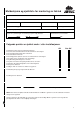
Meldeskjema og sjekkliste for montering av ildsted Tlf. Eiers navn Eiendommens adresse: Sted: Post nr. Ildstedets navn og type: Gnr. Bnr. Maks. effekt i kW Brenseltype Skorsteinstype (eks. tegl, element eller stålskorstein): Høyde fra røykinnføring til skorsteinstopp og innvendig diameter: Meter Dia. Ø Antall ildsteder på skorsteinen: mm Stk.
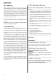
ENGLISH Table of contents Installation manual with technical data 1.0 Relationship to the authorities ............................ 5 2.0 Technical data .................................................... 5 3.0 Safety ................................................................. 6 4.0 Installation ......................................................... 12 5.0 Daily use ............................................................. 21 6.0 Maintenance .....................................................
ENGLISH 3.0 Safety NB! To guarantee optimal performance and safety, Jøtul recommends that its stoves are fitted by a qualified installer (see www.jotul.com for a complete list of dealers). Any modifications to the product may result in the product and safety features not functioning as intended. The same applies to the installation of accessories or optional extras not supplied by Jøtul.
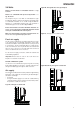
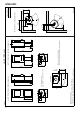
ENGLISH 3.4 Walls Figur 2B, Through the floor and ground plate Distance to walls made of combustible material - see fig. 1a and 1c. Distance to combustible wall protected by firewall: - see fig. 1b and 1d . The fireplace may be used with an uninsulated flue pipe provided the distances between the fireplace and walls made of combustible materials are as shown in fig. 1a and 1c. Distances to combustibile material using semi insulated or shielded flue pipe are also shown in fig. 1a and 1c.
433 1098 (1) (2) 410 952 (2) (1) X Floor plate (1) - Flue pipe center (2) - Outside air connection center (2) 108 Y * Outside air connection ** Min. distance to furniture / combustible material *** Distance to combustible wall with semi-insulated / shielded flue pipe 396 190 *123 (1) 410 (2) (1) (2) (1) Min.
240 *67 * External air supply Integrated 410 50 460 275 *228 500 275 *228 240 50 500 150 560 205 150 *67 *67 External *67 50 686 230 Firewall Combustible wall 120 240 510 50 Jøtul F 134 / F 136 - min. distance to firewall 50 Jøtul F 130 Series 900189-P01 100 Fig.
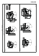
410 Y 952 190 *123 396 433 1098 1098 X Floor plate (1) - Flue pipe center (2) - Outside air connection center (2) (1) * Outside air connection ** Min. distance to furniture / combustible material *** Distance to combustible wall with semi-insulated / shielded flue pipe (1) (2) 108 (2) (1) 190 *123 396 410 (2) (1) (2) (1) Min.
240 *67 * External air supply Integrated 240 External 480 680 275 *228 590 *228 275 50 590 200 *67 240 Jøtul F 135 / F 137 - min. distance to firewall 645 240 200 *67 Jøtul F 130 Series 50 745 340 Firewall 100 900196-P01 Combustible wall 50 240 520 50 Fig.
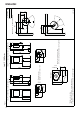
ENGLISH 4.0 Installation • • • • Fig. 4 Before installing the fireplace, check it carefully for any signs of damage. The product is heavy! Ask someone to help you when positioning and installing it. Make sure that furniture and other household items are at a safe distance from the fireplace to protect them from drying out. Do not place anything on the top plate of the stove as this could cause permanent damage to the paint/enamel. 4.
ENGLISH Outside air connection through rear outlet Fig. 7 Fig. 5 A 1. If the external air supply is to be provided by attaching a flex hose (Ø 100 mm) to the outside air connector underneath the burn chamber, knock out the removable cover plate (A) first. A 3. Fit the supplied plate (A) to hide the outside air hose. Outside air connection through the base Fig. 6 Fig. 8 100 mm B C A 2. For attaching the Ø 100 mm outside air hose (A) (optional fitting - item no.
ENGLISH Fig. 9 4.2 Preparations for Jøtul F 136 / F 137 with pedestal Fig. 11 100 mm A B C A 6. For attaching the Ø 100 mm outside air hose (A) (optional fitting - item no. 51012164), refer to the manual (10026187) supplied with the outside air set. Attach the hose to the outside air connector (B) using a hose clip (C). Terminate the insulation approx. 100 mm below the burn chamber. B Fig. 10 8. Lift the front cover (A) on the pedestal up and forwards and put it to one side. 9.
ENGLISH Fig. 12 Outside air connection through rear outlet in pedestal Fig. 13 A 2. Knock out the rear cover (A) in the pedestal with a hammer. 3. Place the stove in its intended position. See fig. 1 for correct placement with regard to safe distances. Fig. 14 A A A A 1. Screw in the supplied height adjustment screws (A) with plastic caps (B) which are in the bag of screws. NB: If using the glass floor plate option, the stove must be raised approx.
ENGLISH Outside air connection through the base of the pedestal Fig. 15 B 100 mm 100 mm Fig. 16 C A B C A 2. For attaching the Ø 100 mm outside air hose (A) (optional fitting - item no. 51012164), refer to the manual (10026187) supplied with the outside air set. Attach the hose to the outside air connector (B) using a hose clip (C). Terminate the insulation approx. 100 mm below the burn chamber. 3. Replace the front cover on the pedestal. 4.
ENGLISH • • Please note that it is extremely important for connections to have a degree of flexibility. This is to prevent any movement in the installation leading to the formation of cracks. For recommended chimney draught, see «2.0 Technical Data». For flue pipe dimension see “2.0 Technical Data”. NB: The chimney’s diameter must be at least just as big as the flue pipe. 4.4 Fitting a flue pipe with a top outlet The product is supplied from the factory with the smoke outlet fitted for the top outlet.
ENGLISH 4.5 Fitting a flue pipe with a rear outlet Fig. 21 The product is supplied from the factory with the smoke outlet fitted for the top outlet. To use the rear outlet, proceed as follows Fig. 19 A A A 3. Knock out the cover (A) with a hammer. 1. Remove the four screws (A). Fig. 20 Fig. 22 B B B B A 2. Unhook the rear plate (B). 18 4. Lift off the inner rear plate (A). 5. Then clip out the cover at the four points shown (B).
ENGLISH Fig. 23 Fig. 25 B B D A A A A B 6. Cut the supplied gasket (A) into three lengths to fit the tabs. Place the gaskets on the ends on the three 7. tabs on the top cover (B). Fig. 24 A B 11. Fit the smoke outlet (A) to the rear vent and screw it on with the same screws (B) that it was attached with. 12. Fit the smoke outlet cover (C) to the top outlet using the same screws (D) that it was attached with Fig. 26 D D C A B C 8.
ENGLISH Fig. 27 4.6 Performance check Once the product has been assembled, always check the control handles. These should move easily and work in a satisfactory manner. B Fig. 28 A C 15. Place the gasket (B) on the edge of the flue pipe (A). 16. Insert the flue pipe into the rear outlet. Min. Max. Max.
ENGLISH 4.7 Use • Push the ignition vent all the way to the left (fig. 28). Open the air vent (fig. 28) by pushing it to the right. (Use a glove, for example, as the handle can become hot.). Fig. 29 not drawing properly (too much/too little draught). For further information, see «4.4 Chimney and flue pipe» 5.2 Ash removal Jøtul F 130 has an ash pan which makes it easy to remove the ashes. • Only remove ashes when the fireplace is cold.
ENGLISH Jøtul F 130 has a nominal heat output of ca. 4,7 kW. Use of wood, with nominal heat emission: Approx. 1,25 kg/h. Another important factor for proper fuel consumption is that the logs are the correct size. The size of the logs should be: Kindling: Length: Diameter: Amount per fire: Max. 20 cm 2 - 4 cm 6 - 8 stk. Firewood (split logs): Diameter: Intervals for adding wood: Amount per load: Size of the fire: Amount per load: Approx.
ENGLISH 7.0 Service Any unauthorised modifications to the product are prohibited! Only original spare parts may be used! 7.2 Replacing glass and gaskets in the door Fig. 31 7.1 Service / replacing parts of the burnchamber Note! If you use tools, be aware that the vermiculite plates may be damaged by rough treatment. A A Fig. 30 A B B B2 A A D B1 E D C E 1. Baffle: Lift the rear edge of the baffle (A) up and down and twist it out of the burn chamber. 2.
ENGLISH 8.0 Optional equipment Fig. 33 8.2 Outside air connection Ø 100mm - Art. no. 51012164 9.0 Operational problems troubleshooting Poor draught A 1. Check the length of the chimney and that it complies with national laws and regulations. (See also «2.0 Technical data» and «4.0 Installation» (Chimney and flue pipe) in the installation manual for information.) 2. Make sure that the minimum cross section on the chimney is according to «2.0 Technical data» in the installation manual. 3.
ENGLISH 10.0 Recycling 11.0 Guarantee terms 9.1 Recycling packaging 1. Your fireplace is delivered with the following packaging: • A wooden pallet that can be cut up and burned in the fireplace. • Cardboard packaging that should be taken to a local recycling facility. • Plastic bags that should be taken to a local recycling facility. 9.2 Recycling the fireplace The fireplace is made of: • Metal that should be taken to a local recycling facility. • Glass that should be disposed of as hazardous waste.
FRANCAIS Sommaire 1.0 Relations avec les autorités ....................... 26 2.0 Données techniques .................................. 26 3.0 Sécurité ........................................................27 4.0 Installation ..................................................33 5.0 Utilisation au quotidien............................. 42 6.0 Entretien ......................................................43 7.0 Maintenance .............................................. 44 8.
FRANCAIS Nous vous recommandons de vous inspirer des règles du D.T.U. 24.2.2. Vous devez lire entièrement le présent manuel avant de commencer l’installation et le conserver pendant toute la durée de l’utilisation du poêle. 3.0 Sécurité Remarque : Afin d’assurer un niveau de rendement et de sécurité optimal, l’installation d’un poêle Jøtul doit être confiée à un installateur qualifié (voir www.jotul.com pour la liste complète de nos revendeurs).
433 1098 (1) (2) 410 108 952 (2) X Plaque de sol (1) - Axe du conduit (2) - Axe air combustion par le sol (2) (1) 1098 Y (1) (2) 410 (2) (1) (2) (1) Dimensions minimales de la plaque de sol X/Y = Conformes aux lois et règlements en vigueur. * Amenée d’air frais ** Distance minimale par rapport aux meubles/ matériaux combustibles *** Remarque : Les distances minimales s'entendent avec une cheminée semi-isolée ou un conduit de raccordement isolé jusque contre le produit.
240 *67 * Amenée d’air frais Intégré 410 50 460 275 *228 585 *228 275 240 50 475 150 560 205 *67 150 50 686 *67 566 240 510 50 50 230 100 900189-P00 Mur ininflammable Mur inflammable Jøtul F 134 / F 136 - distance minimale par rapport au mur en matériau combustible protégé par un pare-feu 120 Extern *67 Jøtul F 130 Series 50 Fig.
410 Y 1098 X Plaque de sol (1) - Axe du conduit (2) - Axe air combustion par le sol (2) (1) 190 *123 (1) (2) 410 (2) (1) (2) (1) Dimensions minimales de la plaque de sol X/Y = Conformes aux lois et règlements en vigueur. 396 952 190 *123 396 433 1098 * Amenée d’air frais ** Distance minimale par rapport aux meubles/ matériaux combustibles *** Remarque : Les distances minimales s'entendent avec une cheminée semi-isolée ou un conduit de raccordement isolé jusque contre le produit.
240 *67 240 * Amenée d’air frais Intégré 480 680 275 *228 656 *228 275 50 590 *67 200 645 240 200 *67 240 Extern Jøtul F 135 / F 137 - distance minimale par rapport au mur en matériau combustible protégé par un pare-feu Jøtul F 130 Series 50 745 340 100 900196-P00 Mur ininflammable Mur inflammable 50 150 596 240 520 50 50 50 Fig.
FRANCAIS Amenée d’air frais Figur 2C, par le sol et la cave L’air utilisé pour la combustion doit être renouvelé en permanance. Ceci est particulièrement important dans une maison avec ventilation mécanique. Plusieurs méthodes sont possibles. Le plus important est de faire arriver l’air dans la pièce où le poêle est installé. Le clapet de mur extérieur doit être placé le plus près possible du poêle et doit pouvoir se fermer lorsque le poêle n’est pas utilisé.
FRANCAIS Fig. 4 4.0 Installation • • • Avant l’installation, vérifiez que le produit ne présente aucun dommage visible. Le produit est lourd ! Prévoyez de l’aide pour sa mise en place et son installation. Assurez-vous qu’aucun meuble ou autre objet ménager ne se trouve trop près du poêle, auquel cas celui-ci pourrait les sécher. 4.
FRANCAIS Raccordement de l’air extérieur à travers l’aération arrière Fig. 7 Fig. 5 A A 1. Si l’air extérieur est fourni en reliant le conduit flexible (Ø 100 mm) au raccord d’air frais sous le foyer, retirer d’abord les caches amovibles (A). 3. Fixer la plaque fournie (A) pour cacher le flexible d’air extérieur. Fig. 6 Raccordement de l’air extérieur à travers le socle Fig. 8 100 mm B C A 2.
FRANCAIS Fig. 9 4.2 Préparations pour Jøtul F 136 / F 137 avec piédestal Fig. 11 100 mm A B C A 6. Pour fixer le flexible d’air extérieur Ø 100 mm (A) (fixation facultative - élément n°51012164), consulter le manuel fourni avec le kit d’air extérieur. Fixer le tuyau au connecteur d’air extérieur (B) à l’aide d’un collier de serrage (C). Fixer l’isolant jusqu’à env. 100 mm au-dessous du poêle. B Fig. 10 8. Retirer le cache avant (A) du piédestal en le soulevant vers le haut et vers l’avant.
FRANCAIS Fig. 12 Raccordement de l’air extérieur à travers l’aération arrière du piédestal Fig. 13 A 2. Défoncer le cache arrière (A) du piédestal à l’aide d’un marteau. 3. Placer le poêle à l’emplacement voulu. Voir fig. 1 pour l’emplacement correct en ce qui concerne les distances de sécurité. Fig. 14 A A A A 1. Installer les vis de réglage de la hauteur (A) avec des bouchons en plastique (B) placés dans le sachet de vis.
FRANCAIS Fig. 15 Raccordement de l’air extérieur à travers le piédestal B 100 mm 100 mm Fig. 16 C A B C A 5. Pour fixer le flexible d’air extérieur Ø 100 mm (A) (fixation facultative - élément n°51012164), consulter le manuel fourni avec le kit d’air extérieur. Fixer le tuyau au connecteur d’air extérieur (B) à l’aide d’un collier de serrage (C). Fixer l’isolant jusqu’à env. 100 mm au-dessous du poêle. 6. Remonter le cache avant du piédestal. 7.
FRANCAIS • • • Utiliser un coude de conduit doté d’une trappe ou un té ou siphon afin de permettre les opérations de ramonage suivant réglement. Veiller à ce que les raccordements soient souples afin d’empêcher toute fissure lors de l’installation. Tirage recommandé; Voir également les sections « 2.0 Données techniques». En cas de tirage trop important, utiliser un clapet ou un modérateur de tirage. 4.
FRANCAIS Fig. 21 4.5 Montage d’un conduit de fumée avec sortie par l’arrière Le produit est livré avec un conduit d’évacuation de la fumée prévu pour une sortie par le haut. Si vous utilisez une évacuation par l’arrière, procédez comme suit : Fig. 19 A A 3. Défoncer le couvercle (A) avec un marteau. A 1. Desserrez les quatre vis (A). Fig. 22 Fig. 20 B B B B A 4. Soulever et enlever les plaques arrière internes (A). 5. Puis détacher le cache aux quatre points indiqués (B). 2.
FRANCAIS Fig. 25 Fig. 23 B B D A A A A B 6. Découper le joint fourni (A) en trois longueurs de manière à s’adapter à la taille des languettes. 7. Placer les joints sur les bords des trois languettes du cache supérieur (B). Fig. 24 A B 11. Fixer la buse (A) à l’évacuation arrière en utilisant les vis d’origine (B). 12. Fixer le cache du conduit d’évacuation de fumée (C) à la sortie par le haut en utilisant les vis d’origine (D). Fig. 26 D D C A B C 8.
FRANCAIS Fig. 27 4.6 Test de fonctionnement Une fois le poêle installé, vérifiez toujours les poignées de commande. Les éléments mobiles doivent fonctionner librement. B Fig. 28 A C 15. Placer le joint d’étanchéité (B) sur le rebord du conduit de fumée (A). 16. Insérer le conduit de fumée dans la sortie arrière Min. Max. Max.
FRANCAIS 4.7 Allumage Risque de surchauffe Pousser la commande d’air d’allumage complètement à gauche (fig. 28). Pousser la commande d’air de combustion (fig. 28) complètement à droite. ( utiliser un gant, par exemple, car les commandes peuvent devenir chaudes). Ne surchauffez jamais le poêle Fig. 29 La surchauffe est provoquée par un excès de combustible et/ou d’air qui donne lieu à un dégagement de chaleur trop important.
FRANCAIS La qualité du bois Par bois de qualité, nous entendons les essences les plus courantes telles que bouleau, épicéa et pin ou hêtre, chêne, érable. Suivant les pays. Les bûches doivent sécher afin que leur teneur en eau ne dépasse pas 20 %. Pour cela, il convient de couper le bois à la fin de l’hiver. Fendez-les et empilez-les pour permettre à l’air de bien circuler. Recouvrez les piles afin de protéger les bûches de la pluie.
FRANCAIS 6.5 Entretien de la surface externe La couleur des produits peints peut se ternir après plusieurs années d’utilisation. Avant d’appliquer une nouvelle couche de peinture, brosser et laver la surface peinte pour en éliminer toutes les particules. 7.2 Remplacement de la vitre et des joints de la porte Fig. 31 7.0 Maintenance A A Toute modification non autorisée du produit est interdite. Utilisez uniquement des pièces de rechange d’origine. 7.
FRANCAIS Fig. 33 8.0 Équipements disponibles en option Kit d’amenée d’air frais Ø 100 mm Ø 100mm - Art. no. 51012164 9.0 Dysfonctionnements – Causes et dépannages A Tirage faible A 9. Retirer les joints (A) de la porte. Bien nettoyer la rainure du joint et coller le nouveau joint en place. ATTENTION ! Mettre seulement un peu colle au fond de la gorge. La colle ne doit pas déborder du joint. Ne pas couper le jount à longueur avant de la poser. 10.
FRANCAIS 10.0 Recyclage Notre garantie commerciale ne couvre pas : • 9.1 Recyclage de l’emballage • • • • Votre poêle est livré avec les emballages suivants : Une palette en bois qui peut être sciée et brûlée dans le poêle. Des emballages en carton qui doivent être déposés dans une station de recyclage près de chez vous. Des sacs en plastique qui doivent être déposés dans une station de recyclage près de chez vous, ou dans poubelle. 9.
NEDERLANDS Inhoudsopgave 1.0 Wettelijke voorschriften Een haard moet in overeenstemming met de wetten en voorschriften van uw land worden geïnstalleerd. Alle lokale bepalingen, inclusief de bepalingen die betrekking hebben op nationale en Europese normen, zullen worden nageleefd bij het installeren van het product. 1.0 Wettelijke voorschriften ........................... 47 2.0 Technische gegevens .............................. 47 3.0 Veiligheid .................................................
NEDERLANDS 3.0 Veiligheid NB! Om zeker te zijn van optimale prestaties en veiligheid, dienen de kachels van Jøtul altijd te worden geplaatst door een gekwalificeerde installateur. Aanpassingen aan het product door de distributeur, installateur of consument kunnen ertoe leiden dat het product en de beveiligingen niet naar behoren functioneren. Hetzelfde geldt voor de installatie van niet door Jøtul geleverde accessoires of optionele extra’s.
410 1098 108 952 X Vloerplaat 433 (1) (2) 410 (2) (1) (2) (1) Minimale afmetingen voor de vloerplaat X / Y in overeenstemming met nationale wet- en regelgeving (1) - Centrum kachelpijp (2) - Centrum externe luchtaansluiting (2) 952 Y 433 1098 Jøtul F 136 (met voetstuk en zonder zijglas) 108 * Externe luchtaansluiting ** Minimale afstand tot meubilair/ brandbare materialen *** De minimale afstanden tot brandbare muur gelden voor een semi-geïsoleerde schoorsteen of afgeschermde kachelpi
240 *67 240 * Externe luchtaansluiting Geïntegreerd 410 *67 Extern 50 460 275 *228 585 *228 275 50 475 150 240 510 240 50 Jøtul F 134 / F 136 - minimale afstand tot brandmuur 560 205 150 *67 Jøtul F 130 Serien *67 50 686 100 900189-P00 Brandmuur Brandbare muur 230 120 50 50 Afb.
(1) (2) 410 (2) 433 1098 X Vloerplaat 190 *123 396 (1) (2) 410 (2) (1) (2) (1) Minimale afmetingen voor de vloerplaat X / Y in overeenstemming met nationale wet- en regelgeving (1) - Centrum kachelpijp (2) - Centrum externe luchtaansluiting (2) 108 (1) 952 952 190 *123 396 1098 Jøtul F 137 (met voetstuk en zijglas) 108 433 * Externe luchtaansluiting ** Minimale afstand tot meubilair/ brandbare materialen *** De minimale afstanden tot brandbare muur gelden voor een semi-geïsoleer
*67 240 *67 240 * Externe luchtaansluiting Geïntegreerd Extern 480 680 275 *228 656 *228 275 50 590 240 520 50 Jøtul F 135 / F 137 - minimale afstand tot brandmuur 200 *67 240 Jøtul F 130 Serien 645 240 200 *67 52 50 745 340 100 900196-P00 Brandmuur Brandbare muur 50 Afb.
NEDERLANDS Toevoer van frisse lucht Figur 2C, via de vloer en kelder De lucht die gebruikt wordt voor verbranding in een goed geïsoleerd huis moet worden ververst. Dit is met name van belang voor huizen met mechanische ventilatie. Deze luchtverversing kan op een aantal manieren worden bereikt. Het belangrijkste is dat er lucht wordt aangevoerd naar de ruimte waar de kachel geplaatst is.
NEDERLANDS 4.0 Installatie Afb. 4 NB: Controleer voordat u met de installatie begint of de haard onbeschadigd is. NB: Het product is zwaar! Zorg voor hulp bij het plaatsen en installeren. Let op! Zorg ervoor dat meubilair en andere huishoudartikelen niet zo dicht bij de kachel staan dat ze kunnen uitdrogen. NB: Lees de installatie- en bedieningsinstructies aandachtig door voordat u de haard plaatst! 4.
NEDERLANDS Externe luchtaansluiting door de achteruitlaat Afb. 7 Afb. 5 A 1. Als in de externe luchttoevoer moet worden voorzien door een flexibele slang (Ø 100 mm) aan te sluiten op de externe luchtaansluiting onder de verbrandingskamer, moet u eerst de verwijderbare afdekplaat (A) losslaan. A 3. Plaats de meegeleverde plaat (A) om de externe luchtslang te verbergen Externe luchtaansluiting via de basis Afb. 6 Afb. 8 100 mm B C A 2.
NEDERLANDS Afb. 9 4.2 Voorbereidingen voor Jøtul F 136 / F 137 met voetstuk Afb. 11 100 mm A B C A 6. Zie voor het bevestigen van de slang (Ø 100 mm) voor de buitenlucht (A) (optionele fitting - artikelnr. 51012164) de handleiding bij de externe luchtset. Sluit de slang met een slangklem (C) aan op de externe luchtaansluiting (B). Laat de isolatie ca. 100 mm onder de verbrandingskamer eindigen. B Afb. 10 1. Til de voorafdekking (A) op het voetstuk omhoog en naar voren en leg deze opzij. 2.
NEDERLANDS Afb. 12 Externe luchtaansluiting door de achteruitlaat in het voetstuk Afb. 13 A 2. Tik de achterafdekking (A) in het voetstuk er met een hamer uit. 3. Plaats de kachel op zijn beoogde plek. Zie afb. 1 voor de juiste plaatsing met het oog op veilige afstanden. Afb. 14 A A A A 1. Draai de meegeleverde hoogtestelschroeven (A) met plastic doppen (B), die in de zak met schroeven zitten, aan.
NEDERLANDS Afb. 15 Externe luchtaansluiting via de basis van het voetstuk B 100 mm 100 mm Afb. 16 C A B C A 2. Zie voor het bevestigen van de slang (Ø 100 mm) voor de buitenlucht (A) (optionele fitting - artikelnr. 51012164) de handleiding bij de externe luchtset. Sluit de slang met een slangklem (C) aan op de externe luchtaansluiting (B). Laat de isolatie ca. 100 mm onder de verbrandingskamer eindigen. 3. Zet de voorafdekking terug op het voetstuk. 1.
NEDERLANDS • • Let op: het is zeer belangrijk dat de aansluitingen enigszins flexibel zijn. Zo voorkomt u dat kleine verplaatsingen tijdens de installatie tot vervorming of barsten leiden. Zie «2.0 Technische gegevens» voor de aanbevolen schoorsteentrek. Voor afmetingen van de kachelpijp met de relevante doorsnede, zie “2.0 Technische gegevens”. NB! De minimaal aanbevolen schoorsteenlengte is 3,5 m, gemeten vanaf de ingang van de kachelpijp.
NEDERLANDS Afb. 21 4.5 Een kachelpijp met een achteruitlaat verbinden Het product wordt door de fabriek geleverd met een rookuitlaat als bovenuitlaat. Als u een achteruitlaat wilt, gaat u als volgt te werk: Afb. 19 A A A 3. Tik de afdekking (A) er met een hamer uit. 1. Verwijder de vier schroeven (A). Afb. 22 Afb. 20 B B B 2. Haak de achterplaat (B) los. 60 B A 4. Til de binnenste achterplaat (A) eruit. 5. Knip vervolgens de afdekking uit op de vier aangegeven punten (B).
NEDERLANDS Afb. 25 Afb. 23 B B D A A A A B 6. Snijd de meegeleverde pakking (A) in drie stukken om ze af te passen op de uitsteeksels. Plaats de pakkingen op de uiteinden van de drie uitsteeksels op de bovenafdekking (B). Afb. 24 A B 10. Bevestig de rookuitlaat (A) aan de achteruitlaat en schroef hem met dezelfde schroeven (B) vast als waarmee hij eerder was bevestigd. 11.
NEDERLANDS Afb. 27 4.6 Prestatiecontrole Als het product is gemonteerd, moet u altijd de bedieningshendels controleren. Deze moeten makkelijk bewegen en goed werken. B Afb. 28 A C 15. Plaats de pakking (B) op de rand van de kachelpijp (A). 16. Breng de kachelpijp aan in de achteruitlaat. Min. Max. Max.
NEDERLANDS 4.7 Gebruiken As verwijderen • De Jøtul F 130 heeft een aslade waarmee het eenvoudig is om as te verwijderen. • Verwijder de as niet voordat de haard koud is. • Schraap het as over het rooster op de bodem, zodat het as in de aslade valt. Gebruik een handschoen of iets dergelijks om uw hand te beschermen. Pak de hendel van de aslade vast en haal de aslade eruit. Zorg ervoor dat de aslade nooit zo vol is dat er geen as meer door het rooster in de aslade kan vallen.
NEDERLANDS dergelijke vloeistoffen om het vuur aan te steken. Dit kan leiden tot ernstig persoonlijk letsel en schade aan het product. 6.3 Kachelpijpen vegen tot aan de schoorsteen Brandstofverbruik Kachelpijpen moeten worden geveegd via een veegluik voor de kachelpijp of via de deuropening. Eerst moet een van de schotten worden verwijderd om dit te kunnen doen. De Jøtul F 130 heeft door zijn efficiëntie een nominale capaciteit van 4,7 kW.
NEDERLANDS 7.0 Groot onderhoud Waarschuwing! Er mogen geen wijzigingen aan het product worden uitgevoerd die niet door ons zijn goedgekeurd! Gebruik uitsluitend originele reserveonderdelen! 7.2 Glas en pakking in de deur vervangen Afb. 31 7.1 Onderhoud/onderdelen vervangen in de verbrandingskamer A NB: Wees uiterst voorzichtig met het gereedschap! De vermiculietplaten kunnen beschadigd raken als u ze ruw behandelt. A Afb. 30 B A B B2 A A D B1 E D C E 1.
NEDERLANDS Afb. 33 8.0 Optionele extra’s 8.1 Externe luchtaansluiting Ø 100mm - Cat. nr. 51012164 9.0 Gebruiksproblemen problemen oplossen Slechte trek A Controleer de lengte van de schoorsteen en of hij voldoet aan de geldende wetten en voorschriften. Zorg ervoor dat de minimale afmetingen van de schoorsteen overeenkomen met de beschrijving in «2.0 Technische gegevens». Controleer of de afvoer van gassen niet wordt belemmerd, zoals bijvoorbeeld door takken of bomen, enzovoort.
NEDERLANDS 10.0 Recycling 10.1 Recyclen van de verpakking • • • • Uw kachel wordt in de volgende verpakking geleverd: Een houten pallet dat in stukken gesneden en in de kachel verbrand kan worden. Een kartonnen verpakking die naar een plaatselijke faciliteit voor recyclen van materialen gebracht moet worden. Plastic zakken die naar een plaatselijke faciliteit voor recyclen van materialen gebracht moet worden. 10.
Cat.no. 10051536 -P00 Jøtul AS, Nov, 2016 Jøtul pursue a policy of constant product development. Products supplied may therefore differ in specification, colour and type of accessories from those illustrated and described in the brochure. Jøtul vise sans cesse à améliorer ses produits. C’est pourquoi, il se réserve le droit de modifier les specifications, couleurs et équipements sans avis prélable. Jøtul een beleid van voortdurende productontwikkeling.