Jøtul F 3 USA Jøtul F 3 USA Installation and Operating Instructions for the USA and Canada Kindly save these instructions for future reference.
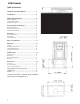
USA/Canada Table of contents: Standards and Safety Notices ........................... 3 Installations ....................................................... 4 Chimney Requirements ..................................... 6 Masonry Chimney ....................................................................... 6 Prefabricated Chimney .............................................................. 6 Wall pass-throughs .....................................................................
USA/Canada Installation and Operation Instructions for USA/Canada Installation et fonctionnement pour Canada Safety notice: If this solid fuel room heater is not properly installed, a house fire may result. For your safety, follow the installation directions. Contact local building or fire officials about restrictions and installation inspection requirements in your area. Save these instructions for future reference.
USA/Canada Notices • Be sure to read this entire manual before you install or use your new Jøtul F 3. • If this room heater is not properly installed, a house fire may result. To reduce the risk of fire, follow the installation instructions. Failure to follow these instructions may result in property damage, bodily injury, or even death. • Jøtul recommends that you have your new Jøtul F 3 installed by a professional installer of solid fuel burning appliances.
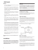
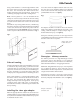
USA/Canada Using a claw hammer or a small sledge hammer strike the center of the 6” “knock-out” disc from the outside of the stove. The “knock-out” disc will break into four wedges and may need to be tapped out. Touch up any remaining sharp edges with a file or hand grinder. Insert the end of the adapter with the four holes into the stove. These holes allow the adaptor to be attached to the stove’s internal collar, using the nuts and bolts provided with the stove. See figure 3. Fig.
USA/Canada This prevents any amount of condensed or liquid creosote from running down the outside of the pipe or the stove top. All joints, including the flue collar connection must be secured with three sheet metal screws to ensure that the sections do not separate. For the best performance the chimney connector should be as short and direct as possible, with no more than two 90° elbows. The maximum horizontal run is 36” and a recommended total length of stove pipe should not exceed 10 feet.
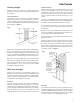
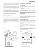
USA/Canada Chimney height Whether a masonry chimney or prefabricated metal chimney is used it must be the required height above the roof line. The requirement is: The chimney must be at least 3 feet higher than the highest point where it passes through the roof and at least 2 feet higher than the highest part of the roof or structure that is within 10 feet of the chimney, measured horizontally. See figure 6. Fig.
USA/Canada Common method This method requires the removal of all combustible materials from at least 18” (457mm) around the chimney connector’s proposed location. With a 6” round liner the minimum area required would be 43” x 43” square. It is important to remember to locate the pass-through at least 25” from the ceiling to maintain the proper clearance to combustibles. The space that is cleared of combustible materials must then remain empty. Sheet metal panels can then be used to cover the area.
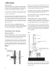
USA/Canada If the chimney liner is too large to accommodate the stove, an approved relining system must be installed to resize the flue. Clearances to combustibles A new sheet metal damper block-off plate must be installed around the connector pipe at the damper frame and sealed with the proper sealant (usually high-temp silicone). Floor protection under the Jøtul F 3, must be one of the following: 1. Any non combustible material with an insulative R value of 1.1.
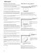
USA/Canada Clearances to walls and ceilings Wall Shield for close clearance The following clearances have been tested to UL and ULC standards and are the minimum clearances specifically established for the Jøtul F 3. (See next page) Combustible wall Wall shield The following charts and diagrams give the required clearances you must maintain when installing the Jøtul F 3 near combustible surfaces. A combustible surface is anything that can burn (i.e. Sheet rock, wall paper, wood, fabrics etc.).
USA/Canada Jøtul F 3 Clearances Stove Clearances Top vent/vertical Unprotected Surfaces Protected Surfaces per NFPA 211 or CAN/CSA-B365-M Side Rear Rear heatshield with Single wall pipe 24" 610mm 25" 18" 635mm 460mm Corner Rear heatshield with Double wall pipe or shields Stove Clearances Rear Vent/Horizontal Side Rear Corner 10" 14" 255mm 355mm 10" 255mm 18" 10" 14" 460mm 255mm 355mm 6" 6" 150mm 150mm 6" 150mm Unprotected Surfaces Protected Surfaces per NFPA 211 or CAN/CSA-B365-M Side
USA/Canada Notice Accessories for woodstoves for clearance reduction have been developed by many manufacturers. If not following the methods of the installation codes, be sure that any accessory you choose has been tested by an independent laboratory and carries the laboratory’s testing mark. Make sure to follow all of the manufacturer’s instructions. Always contact your local building inspector or fire officials about restriction and requirements in your area.
USA/Canada Operation Before building a fire in your new Jøtul F 3, please read the following section carefully and completely. Do not burn First this stove is designed to burn natural wood only, wood that has been air-dried for a period of 6 to 14 months will provide the cleanest most efficient heat. When first starting a fire: The primary control lever should be at the far right position, and the start-up air lever should be in the far right position.
USA/Canada Never overfire the stove If any part of the stove or chimney glows, you are overfiring, and a house fire or serious damage to the stove or chimney could result. Immediately close down the air control if you notice this condition. Starting and maintaining a fire Burn only solid wood directly on the bottom grate of the stove, do not elevate the fire in any way. The ash pan door on the stove must always be securely closed when the stove is in operation.
USA/Canada counterclockwise to unlatch the door and clockwise to latch the door. Remove the ash pan. When the stove is in operation always close the ash pan door before leaving to dispose of the ashes. The ashes should be placed in a metal container equipped with a tight sealing lid. The container should be placed on a noncombustible floor or on the ground, well away from all combustible materials, pending final disposal.
USA/Canada can be easily removed then the seal is too loose. Check several spots around the door, and repeat the procedure on the ash pan door as well. If gaskets need to be replaced, scrape out the old gasket and cement and clean the area with a wire brush. Apply a small bead of cement and push in the new gasket. After closing and latching the doors wipe clean, any excessive cement that has come from beneath the gasketing.
USA/Canada Appendix A: Alternate floor protection All floor protection materials must be non-combustible ie. Metal, brick, stone, mineral fiber boards). Any combustible material may not be used. The easiest means of determining if a proposed alternate floor material meets requirements listed in this manual is to follow this procedure. R-value = thermal resistance K-value = thermal conductivity C-value = thermal conductance 1. Convert the specification to r-value; a.
USA/Canada
Part list for Jøtul F 3 No 1 2 2b 3 4 5 6 7 8 9 10 11 12 13 14 15 16 17 18 19 20 21 22 23 24 26 27 28 29 30 31 32 33 34 35 37 38 39 40 41 42 43 44 45 46 48 49 50 51 52 53 54 55 57 58 Description, Dim./Spec. Nut brass, M6x20 DIN 1587 Heat shield aluz. f/ivory en. Heat shield Screw, M6x16 DIN 965 Nut , M6 DIN 934 Screw collar, M6x16 st.5.6 ubeh. Cover smoke outlet rear Traverse bar to cover smoke outlet rear Top plate compl. w/ cover smoke outlet Gasket, LD 375-2 9.
Cat.no. 128744 Draw.no. 4-3431-P03 Møklegaards Trykkeri as, June 04 Jøtul pursue a policy of constant product development. Products supplied may therefore differ in specification, colour and type of accessories from those illustrated and described in the brochure. Jøtul vise sans cesse à améliorer ses produits. C’est pourquoi, il se réserve le droit de modifier les specifications, couleurs et équipements sans avis prélable.