Jøtul GF 3 CF 2 Conventional Flue Gas Stove Installation and Operation Instructions WARNING: If the information in these instructions is not followed exactly, a fire or explosion may result causing property damage, personal injury or death. – Do not store or use gasoline or other flammable vapors and liquids in the vicinity of this or any other appliance. – WHAT TO DO IF YOU SMELL GAS • Do not try to light any appliance. • Do not touch any electrical switch; do not use any phone in your building.
Jøtul GF 3 CF 2 INSTALLATION SIGNATURE FORM With proper usage and maintenance, this appliance will serve its owner adequately for many years. Please contact your Jøtul dealer for assistance if any problems should arise with your Jøtul appliance. Save this user manual and make sure it is available for service personnel. Annual service - year 8 Company: Model Name: Jøtul GF 3 CF 2 Service details: Sign.: Date: Service details: Annual service - year 9 Company: Sign.: Date: Serial No.
THIS OWNER’S MANUAL PROVIDES INFORMATION TO ENSURE SAFE INSTALLATION AND EFFICIENT, DEPENDABLE OPERATION OF YOUR STOVE. PLEASE READ THESE INSTRUCTIONS IN THEIR ENTIRETY AND MAKE THEM AVAILABLE TO ANYONE USING OR SERVICING THIS GAS STOVE. Table of Contents 1. Technical Information ......................... 4 2. General Information ........................... 5 3. Safety Information ............................... 5 4. Installer Information ........................... 6 5. User Information ..................
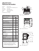
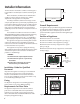
Jøtul GF 3 CF 2 Technical Information C L 292 mm Material: Cast iron/steel Finish: Blue Black enamel or Matte Black paint Flue outlet: Top or Rear Vent system: BV-standard system Weight: Approx. 71 kg (product) PIN: 0063BS5908 114 mm C L 420 mm Product dimensions: See fig. 1. 584 mm Figure 1. Top view dimensions.
General Information Safety Precautions This product has been approved to the European This appliance must be installed in accordance with the Standard EN 613:2000 and is in accordance with EC Gas Appliances Directive (90/396/EEC). The Flue must be checked for soundness and swept prior to installation it should only be used if clean and in good order. Before installation, ensure that the local distribution conditions and the adjustment of the appliance are compatible.
Installer Information The Flue must be checked for soundness and swept prior to installation it should only be used if clean and in good order. 435 mm Before installation, check that the local distribution conditions, nature of the gas and pressure, and the adjustment of the appliance are compatible. Assembly, installation, maintenance and gas conversion (if required) must be performed by a qualified person in accordance with the instructions for assembly, Installation and use enclosed with the product.
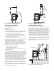
Vent Height off Draft Hood: Min. 2.15 m (7) Max. 3.7 m (35) 520 mm C L 635 mm (25) Draft Hood 550 mm (21 5/8) Figure 7. Clearance to a combustible shelf. Figure 8. Vent height requirements. Flue System Installation Closure Plate Installation Flue outlet (spigot) dimensions: Internally = 128 mm Externally = approx. 131 mm It is permissible to install this appliance using a closure plate installation similar to traditional outset gas fires. See diagrams (1 E-F) on page 28.
All brick flues or any flue previously used with solid fuel or gas appliances must be left with the appropriate debris collection volume below the flue spigot of the stove of 12 litres minimum minimum, and depth of 250mm minimum below the spigot as shown in fig. 9..
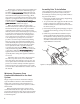
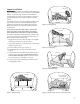
PN 220729 Logset Installation Brick Kit Note: Install the optional Antique Brick Kit 155370 before installing the log set. See instructions supplied with that kit. The GF 3 CF2 log set must be installed before operating the burner. The log set includes four log pieces, packaged inside the firebox, and a quantity of ceramic embers. To install the log set, remove the packaging and place the parts inside the firebox as illustrated in the diagrams below. Do not handle the log set with your bare hands.
Gas Installation Commissioning Gas installation must only be performed by qualified personnel. It is important to adhere to national and local regulations that apply. In the UK these include BS5440 Pt 1&2 and BS5871 in Ireland. Testing the Flue System The LPG gas container must be stored/installed according to national regulations. The gas container must have a pressure regulator that reduces the pressure to the required level.
Regulating the Pilot Flame Figure 17. The pilot flame should have three flames as shown in fig. 17. The two thermo-element sticks should be surrounded by two of the flames as shown in fig. 18. The flames should be stable and the colour mainly blue. If you detect a deviation from this, turn off the pilot flame and call for service. Proper pilot flame / carry-over port alignment. Adjusting the Burner Burner adjustments must only be performed by qualified personnel.
User Information General Operating Instructions Assembly, installation, maintenance and gas conversion (if required) must be performed by a qualified person in accordance with the instructions for assembly, Installation and use enclosed with the product. The installation may only be operated after it has been inspected by a qualified person and a certificate of completion has been issued.
B ON OFF TSTAT A D E C Figure 21. Valve Controls. Figure 22. Burner Controls. 4. Push in the gas control knob (B) as far as possible and hold it in. Simultaneously, push in the ignition knob (A) until the spark ignites the pilot flame located to the right rear corner of the burner.. Adjusting the Heat Setting 5. Continue to hold in the gas control knob for approx. 20 seconds after the pilot flame has been lit. Then let go of the knob. It should pop back out and the pilot flame should remain lit.
Troubleshooting When No Spark is Generated at the Pilot Head It is uncommon for the Piezo spark ignitor (fig 23-A) to fail, unless it has mechanical damage. If the spark is not conducted forward, it could be the result of a break in the electrical circuit leading up to the pilot head. The spark is small or weak if there is too much resistance from a bent wire (E), or if corrosion appears at the electrode (G) or the pilot head (H). This could result in insufficient heat to light the gas.
When There is No Gas Flow To The Pilot Head Thermocouple (Fig.24) and Thermopile (Fig. 25) This is the trouble-shooting procedure for the gas supply: Check if all gas connections are sealed by using strong soapy water (avoid synthetic soaps). Be certain all valves from the gas tank/cylinder are fully open. A thermocouple is in principle a thermal generator and consists of a copper wire (copper-nickel alloy) and an iron wire twisted together.
When There is No Gas Supply to the Burner. Figure 24. Thermocouple system check. This is the trouble-shooting procedure for the electrical components: 1. Make sure the control knob on the valve is set to “ON”. Check the position on the “ON/OFF/Thermostat” switch at the back of the appliance. It should be set to the ON position. 2. Make sure the wire from the valve to the “ON/OFF/ STAT” switch is connected correctly. This is the trouble-shooting procedure for the thermopile (fig. 25): 1.
Burner Orifice Figure 26. Check main burner orifice for debris blockage. Burner pan is removed.
13 Figure 27. 23 22 2 8 9 10 1 11 12 14 15 16 17 18 89 86 3 85 24 84 87 25 91 83 26 92 27 31 28 24 30 93 81 90 32 94 88 82 33 34 80 39 6 40 41 42 43 44 35 36 37 38 68 69 70 71 72 73 74 75 76 77 78 79 45 46 47 67 48 51 49 50 52 54 55 56 ONLY USE REPLACEMENT PARTS PROVIDED BY AN AUTHORIZED JØTUL DEALER.
Jøtul GF 3 CF 2 Parts List Cast Iron Parts Matte Black Blue Black Enamel Ivory Enamel Brown Majolica Enamel Blue Majolica Enamel 1. 2. 3. 4. 5. 6. 7. 10203292 10390092 10192592 10390192 10390492 10390292 10390392 102033 10390027 101966 110390127 10390427 10390227 10390327 10203229 10390029 102251 10390129 10390429 10390229 10390329 10203247 10390047 10192547 10390147 10390447 10390247 10390347 10203248 10390048 10192548 10390148 10390448 10390248 10390348 8. 9. 10. 11. 12. 13. 14. 15. 16. 17.
October 2007 138783_0 This appliance must be installed in conformance with local and national building regulations. Before beginning the installation, it is important that the these instructions be carefully read and understood. Jøtul maintains a policy of continual product development. Consequently, products may differ in specification, color or type of accessories from those illustrated or described in various publications. Jøtul vise sans cesse a ameliorer ses produits.