GA-H110M-S2H GA-H110M-S2H-GSM GA-H110M-S2H DDR3 User's Manual Rev. 1001 GA-H110M-S2H GA-H110M-S2H-GSM GA-H110M-S2H DDR3 For more product details, please visit GIGABYTE's website. To reduce the impacts on global warming, the packaging materials of this product are recyclable and reusable. GIGABYTE works with you to protect the environment.
Motherboard GA-H110M-S2H GA-H110M-S2H-GSM GA-H110M-S2H DDR3 Motherboard GA-H110M-S2H GA-H110M-S2H-GSM GA-H110M-S2H DDR3 Sept. 11, 2015 Sept. 11, 2015 Copyright © 2015 GIGA-BYTE TECHNOLOGY CO., LTD. All rights reserved. The trademarks mentioned in this manual are legally registered to their respective owners. Disclaimer Information in this manual is protected by copyright laws and is the property of GIGABYTE.
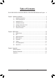
Table of Contents GA-H110M-S2H/GA-H110M-S2H-GSM/GA-H110M-S2H DDR3 Motherboard Layout.....4 Chapter 1 Hardware Installation......................................................................................5 1-1 1-2 1-3 1-4 1-5 1-6 1-7 Installation Precautions..................................................................................... 5 Product Specifications....................................................................................... 6 Installing the CPU...............................
GA-H110M-S2H/GA-H110M-S2H-GSM/GA-H110M-S2H DDR3 Motherboard Layout DDR4_1j/DDR3_1k DVI VGA ATX_12V_2X4 LGA1151 DDR4_2j/DDR3_2k CPU_FAN KB_MS ATX HDMI F_USB30 R_USB R_USB30 GA-H110M-S2H/GA-H110M-S2H-GSM GA-H110M-S2H DDR3 USB_LAN SYS_FAN Realtek GbE LAN ® BAT PCIEX16 1 3 SATA3 0 2 AUDIO PCIEX1_1 iTE® Super I/O Intel® H110 PCIEX1_2 CODEC M_BIOS SPDIF_O F_AUDIO TPM F_USB2 CLR_CMOS F_PANEL F_USB1 COMA Box Contents 55 GA-H110M-S2H, GA-H110M-S2H-GSM, or GA-H110M-S2H DDR3 motherboard
Chapter 1 1-1 Hardware Installation Installation Precautions The motherboard contains numerous delicate electronic circuits and components which can become damaged as a result of electrostatic discharge (ESD). Prior to installation, carefully read the user's manual and follow these procedures: •• Prior to installation, make sure the chassis is suitable for the motherboard. •• Prior to installation, do not remove or break motherboard S/N (Serial Number) sticker or warranty sticker provided by your dealer.
1-2 Product Specifications CPU Support for Intel® Core™ i7 processors/Intel® Core™ i5 processors/ Intel® Core™ i3 processors/Intel® Pentium® processors/ Intel® Celeron® processors in the LGA1151 package (Go to GIGABYTE's website for the latest CPU support list.
Storage Interface Chipset: - 4 x SATA 6Gb/s connectors USB Chipset: - 4 x USB 3.0/2.0 ports (2 ports on the back panel, 2 ports available through the internal USB header) - 8 x USB 2.0/1.
Unique Features Support for APP Center * Available applications in APP Center may vary by motherboard model. Supported functions of each application may also vary depending on motherboard specifications.
1-3 Installing the CPU Read the following guidelines before you begin to install the CPU: •• Make sure that the motherboard supports the CPU. (Go to GIGABYTE's website for the latest CPU support list.) •• Always turn off the computer and unplug the power cord from the power outlet before installing the CPU to prevent hardware damage. •• Locate the pin one of the CPU. The CPU cannot be inserted if oriented incorrectly.
The two DDR4 memory sockets are divided into two channels and each channel has two memory sockets as followingj: Channel A: DDR4_1 Channel B: DDR4_2 The two DDR3 memory sockets are divided into two channels and each channel has two memory sockets as followingk: Channel A: DDR3_1 Channel B: DDR3_2 Due to CPU limitations, read the following guidelines before installing the memory in Dual Channel mode. 1. Dual Channel mode cannot be enabled if only one memory module is installed. 2.
HDMI Port The HDMI port is HDCP compliant and supports Dolby True HD and DTS HD Master Audio formats. It also supports up to 192KHz/24bit 8-channel LPCM audio output. You can use this port to connect your HDMI-supported monitor. The maximum supported resolution is 4096x2160@24 Hz, but the actual resolutions supported are dependent on the monitor being used. •• To set up a dual-display configuration, you must install motherboard drivers in the operating system first.
1-7 Internal Connectors 1 3 2 10 5 4 14 6 7 8 12 13 11 9 1) ATX_12V_2X4 8) SPDIF_O 2) ATX 9) CLR_CMOS 3) CPU_FAN 10) F_USB30 4) SYS_FAN 11) F_USB1/F_USB2 5) SATA3 0/1/2/3 12) COMA 6) F_PANEL 13) TPM 7) F_AUDIO 14) BAT Read the following guidelines before connecting external devices: •• First make sure your devices are compliant with the connectors you wish to connect. •• Before installing the devices, be sure to turn off the devices and your computer.
1/2) ATX_12V_2X4/ATX (2x4 12V Power Connector and 2x12 Main Power Connector) With the use of the power connector, the power supply can supply enough stable power to all the components on the motherboard. Before connecting the power connector, first make sure the power supply is turned off and all devices are properly installed. The power connector possesses a foolproof design. Connect the power supply cable to the power connector in the correct orientation.
5) SATA3 0/1/2/3 (SATA 6Gb/s Connectors) The SATA connectors conform to SATA 6Gb/s standard and are compatible with SATA 3Gb/s and SATA 1.5Gb/s standard. Each SATA connector supports a single SATA device. 7 7 Pin No. 1 2 3 4 5 6 7 SATA3 3 2 1 0 1 1 Definition GND TXP TXN GND RXN RXP GND To enable hot-plugging for the SATA ports, refer to Chapter 2, "BIOS Setup," "Peripherals\SATA Configuration," for more information.
7) F_AUDIO (Front Panel Audio Header) The front panel audio header supports Intel High Definition audio (HD) and AC'97 audio. You may connect your chassis front panel audio module to this header. Make sure the wire assignments of the module connector match the pin assignments of the motherboard header. Incorrect connection between the module connector and the motherboard header will make the device unable to work or even damage it. 9 10 1 2 For HD Front Panel Audio: Pin No. Definition Pin No.
F_USB30 F_ U F_ 10) F_USB30 (USB 3.0/2.0 Header) F_ The header conforms to USB 3.0/2.0 specification and each header can provide two USB ports. For purchasing the optional 3.5" front panel that provides two USB 3.0/2.0 ports, please contact the local dealer. B_ 10 1 Definition D2+ D2GND SSTX2+ SSTX2GND SSRX2+ SSRX2VBUS No Pin 1 11 Pin No. 11 12 13 14 B SS 15 16 17 18 19 20 1 1 Definition VBUS SSRX1SSRX1+ GND SSTX1SSTX1+ GND D1D1+ NC 1 20 Pin No.
13) TPM (Trusted Platform Module Header) You may connect a TPM (Trusted Platform Module) to this header. 19 1 20 2 DEBUG PORT Pin No. Definition Pin No. Definition 1 2 3 4 5 6 7 8 9 10 LCLK GND LFRAME No Pin LRESET NC LAD3 LAD2 VCC3 LAD1 11 12 13 14 15 16 17 18 19 20 LAD0 GND NC NC SB3V SERIRQ GND NC NC SUSCLK 14) BAT (Battery) The battery provides power to keep the values (such as BIOS configurations, date, and time information) in the CMOS when the computer is turned off.
Chapter 2 BIOS Setup BIOS (Basic Input and Output System) records hardware parameters of the system in the CMOS on the motherboard. Its major functions include conducting the Power-On Self-Test (POST) during system startup, saving system parameters and loading operating system, etc. BIOS includes a BIOS Setup program that allows the user to modify basic system configuration settings or to activate certain system features.
2-2 M.I.T. This section provides information on the BIOS version, CPU base clock, CPU frequency, memory frequency, total memory size, CPU temperature and CPU voltage, etc. Whether the system will work stably with the overclock/overvoltage settings you made is dependent on your overall system configurations. Incorrectly doing overclock/overvoltage may result in damage to CPU, chipset, or memory and reduce the useful life of these components.
&& Uncore Frequency Displays the current CPU Uncore frequency. && CPU Flex Ratio Override Enables or disables the CPU Flex Ratio. The maximum CPU clock ratio will be based on the CPU Flex Ratio Settings value if CPU Clock Ratio is set to Auto. (Default: Disabled) && CPU Flex Ratio Settings Allows you to set the CPU Flex Ratio. The adjustable range may vary by CPU. (Default: 20) && Intel(R) Turbo Boost Technology (Note) Allows you to determine whether to enable the Intel CPU Turbo Boost technology.
&& Package C State Limit (Note 1) Allows you to specify the C-state limit for the processor. Auto lets the BIOS automatically configure this setting. (Default: Auto) && CPU Thermal Monitor (Note 1) Enables or disables Intel® Thermal Monitor function, a CPU overheating protection function. When enabled, the CPU core frequency and voltage will be reduced when the CPU is overheated. Auto lets the BIOS automatically configure this setting.
&& Memory Enhancement Settings Provides three different memory performance enhancement settings: Normal (basic performance), Enhanced Stability, and Enhanced Performance. (Default: Normal) && Memory Timing Mode Manual and Advanced Manual allows the Memory Multiplier Tweaker, Channel Interleaving, Rank Interleaving, and memory timing settings below to be configurable. Options are: Auto (default), Manual, Advanced Manual. && Profile DDR Voltage Displays the memory voltage.
`` PC Health Status && Reset Case Open Status Disabled Keeps or clears the record of previous chassis intrusion status. (Default) Enabled Clears the record of previous chassis intrusion status and the Case Open field will show "No" at next boot. && Case Open Displays the detection status of the chassis intrusion detection device attached to the motherboard CI header. If the system chassis cover is removed, this field will show "Yes", otherwise it will show "No".
`` Miscellaneous Settings && Max Link Speed Allows you to set the operation mode of the PCI Express slots to Gen 1, Gen 2, or Gen 3. Actual operation mode is subject to the hardware specification of each slot. Auto lets the BIOS automatically configure this setting. (Default: Auto) && 3DMark01 Enhancement Allows you to determine whether to enhance some legacy benchmark performance. (Default: Disabled) 2-3 System Information This section provides information on your motherboard model and BIOS version.
2-4 BIOS Features && Boot Option Priorities Specifies the overall boot order from the available devices. Removable storage devices that support GPT format will be prefixed with "UEFI:" string on the boot device list. To boot from an operating system that supports GPT partitioning, select the device prefixed with "UEFI:" string.
&& SATA Support All Sata Devices All SATA devices are functional in the operating system and during the POST. (Default) Last Boot HDD Only Except for the previous boot drive, all SATA devices are disabled before the OS boot process completes. This item is configurable only when Fast Boot is set to Enabled or Ultra Fast. && VGA Support Allows you to select which type of operating system to boot. Auto Enables legacy option ROM only. EFI Driver Enables EFI option ROM.
&& Other PCI Device ROM Priority Allows you to select whether to enable the UEFI or Legacy option ROM for the PCI device controller other than the LAN, storage device, and graphics controllers. Disabled Disables option ROM. UEFI Only Enables UEFI option ROM only. (Default) Legacy Only Enables legacy option ROM only. This item is configurable only when CSM Support is set to Enabled.
2-5 Peripherals && Intel Platform Trust Technology (PTT) Enables or disables Intel® PTT Technology. (Default: Disabled) && Initial Display Output Specifies the first initiation of the monitor display from the installed PCI Express graphics card or the onboard graphics. IGFX Sets the onboard graphics as the first display. PCIe 1 Slot Sets the graphics card on the PCIEX16 slot as the first display. (Default) && OnBoard LAN Controller Enables or disables the onboard LAN function.
`` Trusted Computing 2.0 This sub-menu appears only when Intel Platform Trust Technology is set to Enabled. && Security Device Support Enables or disables Trusted Platform Module (TPM). (Default: Enable) && Pending operation To clear TPM related settings, set this item to TPM Clear. (Default: None) && TPM 20 InterfaceType Allows you to select the communication interface for the TPM 2.0 device. Set to External TPM2.0 if you install an Infineon TPM 2.0 module (optional).
2-6 Chipset && VT-d (Note) Enables or disables Intel® Virtualization Technology for Directed I/O. (Default: Disabled) && Internal Graphics Enables or disables the onboard graphics function. (Default: Auto) && DVMT Pre-Allocated Allows you to set the onboard graphics memory size. Options are: 32M~512M. (Default: 64M) && DVMT Total Gfx Mem Allows you to allocate the DVMT memory size of the onboard graphics. Options are: 128M, 256M, MAX.
2-7 Power Management && AC BACK Determines the state of the system after the return of power from an AC power loss. Always Off The system stays off upon the return of the AC power. (Default) Always On The system is turned on upon the return of the AC power. Memory The system returns to its last known awake state upon the return of the AC power. && Power On By Keyboard Allows the system to be turned on by a PS/2 keyboard wake-up event.
&& Soft-Off by PWR-BTTN Configures the way to turn off the computer in MS-DOS mode using the power button. Instant-Off Press the power button and then the system will be turned off instantly. (Default) Delay 4 Sec. Press and hold the power button for 4 seconds to turn off the system. If the power button is pressed for less than 4 seconds, the system will enter suspend mode. && Power Loading Enables or disables dummy load.
2-8 Save & Exit && Save & Exit Setup Press on this item and select Yes. This saves the changes to the CMOS and exits the BIOS Setup program. Select No or press to return to the BIOS Setup Main Menu. && Exit Without Saving Press on this item and select Yes. This exits the BIOS Setup without saving the changes made in BIOS Setup to the CMOS. Select No or press to return to the BIOS Setup Main Menu.
Chapter 3 Appendix Drivers Installation •• Before installing the drivers, first install the operating system. (The following instructions use Windows 8.1 as the example operating system.) •• After installing the operating system, insert the motherboard driver disk into your optical drive. Click on the message "Tap to choose what happens with this disc" on the top-right corner of the screen and select "Run Run.exe." (Or go to My Computer, double-click the optical drive and execute the Run.exe program.
Regulatory Statements Regulatory Notices This document must not be copied without our written permission, and the contents there of must not be imparted to a third party nor be used for any unauthorized purpose. Contravention will be prosecuted. We believe that the information contained herein was accurate in all respects at the time of printing. GIGABYTE cannot, however, assume any responsibility for errors or omissions in this text.
FCC Notice (U.S.A. Only) This equipment has been tested and found to comply with the limits for a Class B digital device, pursuant to Part 15 of the FCC Rules. These limits are designed to provide reasonable protection against harmful interference in a residential installation. This equipment generates, uses, and can radiate radio frequency energy and, if not installed and used in accordance with the instructions, may cause harmful interference to radio communications.
Contact Us GIGA-BYTE TECHNOLOGY CO., LTD. Address: No.6, Baoqiang Rd., Xindian Dist., New Taipei City 231, Taiwan TEL: +886-2-8912-4000, FAX: +886-2-8912-4005 Tech. and Non-Tech. Support (Sales/Marketing) : http://esupport.gigabyte.com WEB address (English): http://www.gigabyte.com WEB address (Chinese): http://www.gigabyte.tw You may go to the GIGABYTE website, select your language in the language list on the top right corner of the website.