3 JT-DMSO2D72 Portable 3-in-one oscilloscope, signal generator and multimeter 1. GENERAL INFORMATION Dear customer, Thank you for choosing our product. Please read the following important information before putting the device into operation. This oscilloscope is compact, portable and flexible. It has a TFT-LCD color display with a resolution of 320 x 240 pixels and adjustable backlight brightness. The maximum real time sampling rate can be up to 250 MSa/s.
. SAFETY INSTRUCTIONS Safety Terms and Symbols: following terms may appear on product: Danger It represents that harms may be caused to you at once if you perform the operation. Warning It represents that latent harms may be caused to you if you perform the operation. Notice It represents that damage may possibly caused to the product or other properties if you perform the operation.
Connect the probe the right way. The probe ground lead is at ground potential. Do not connect the ground lead to an elevated voltage. Check all terminal ratings. To avoid fire or shock hazard, check all ratings and markings on the product. Refer to the product manual for detailed information about ratings before making connections to the product. Do not operate without covers. Do not operate this product with covers or panels removed. Avoid exposed circuitry.
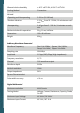
Selectable analog bandwidth limit, typical Typical 20 MHz (reduced to 6 MHz when using a 1x probe) Low frequency response (-3db) ≤ 10 Hz DC gain accuracy 10V/div - 10mV/div ±3% for normal or Trigger Type Edge Mode Auto, Normal, Single Level ± 4 divisions from centre of screen Trigger level accuracy 0,2 div*volts/div within 4 div.
Allowed relative humidity ≤ 40°C: ≤90% RH, 40-50°C: ≤60% RH Cooling Method Convection Altitude: -Operating and Nonoperating 3 000 m (10 000 feet) -Random vibration 0.
Range DC Voltage AC Voltage DC Current Accuracy 400.00mV 4.000V ±(0.8% + 5) 40.00V 400.0V 600.0V ±(1% + 2) Overload protection: 400mV: 250V, other: 600Vrms. 4.000V 40.00V ±(1.2% + 5) 400.0V 600.0V ±(1.5% + 5) Frequency: 40Hz~400Hz; Frequency of 400V and 600V: 40Hz~100Hz 40.00mA ±(1% + 2) 200.0mA ±(1.5% + 2) 4.000A ±(1.8% + 2) 10.
All specifications herein mentioned apply to the series oscilloscopes. Before checking an oscilloscope to see if it complies with these specifications, make sure it meets the following conditions: The oscilloscope must have been operating continuously for twenty minutes under the specified operating temperature. The Do Self Cal operation must be performed through the Utility menu if the operating temperature changes by more than 5°C. The oscilloscope must be within the factory calibration interval.
Adjust the bracket When using the instrument, you can open the support foot to tilt the instrument upward for easy operation and observation. When the instrument is not in use, the user can close the support foot to facilitate placement or handling. After adjusting the rack, the instrument can be suspended on the vertical plane. • Front Panel The following diagram briefly describes the front panel of this oscilloscope.
• The user interface • Functional Check Follow the steps below to perform a quick functional check to your oscilloscope. Power Press the power key and the device starts. Press the power key again, and the device will shut down. Before starting it, please confirm that the battery has enough power. The oscilloscope is supplied with a power adapter with USB-Type-C plug. The input AC power supply is 100~240V, 50~60Hz. The output is 5V@2A.
3. Press the Auto button and you should see within a few seconds a square wave of about 2V peak-to-peak at 1KHz in the display. Repeat the steps to observe CH2. • Probe check Safety When using the probe, keep your fingers behind the guard on the probe body to avoid electric shock. Do not touch metallic portions of the probe head while it is connected to a voltage source. Connect the probe to the oscilloscope and connect the ground terminal to ground before you start any measurements.
You can press Channel button to enter the channel setting menu and select CH1, and select the Probe option that matches the attenuation factor of your probe. Make sure that the Attenuation switch on the probe matches the Probe option in the oscilloscope. Switch settings are 1X and 10X. When the Attenuation switch is set to 1X, the probe limits the bandwidth of the oscilloscope to 6MHz. To use the full bandwidth of the oscilloscope, be sure to set the switch to 10X. 5.
F1/F2/F3/F4: Multi function key, in each menu mode, is responsible for selecting corresponding menu items in the screen. Shortcut keys. Long press this button to enter the menu, and choose shortcut key function; After setting, press this button single time to respond to the corresponding function. In scope, stop or run the waveform acquisition; In DMM, hold the measuring data or update data; In generator, turn on or off the waveform output. Power key.
• Automatic set Auto set is one of the advantages digital oscilloscopes have. When you push the Auto button, the oscilloscope will identify the type of waveform (sine or square wave) and adjust controls according to input signals so that it can accurately display the waveform of the input signal. Functions Settings The Auto function examines all Cursor Off channels for signals and displays Display Format Set to YT corresponding waveforms.
Long press button, to enter Short key setting menu, and select Default. Press button, pops up the prompt to recall the default settings on the screen, now press F1 to confirm. The oscilloscope will display the CH1 waveform and remove all the others. Press F4 to cancel. The table below gives the options, buttons and controls that change settings at default setup.
Vertical System Vertical system can be used to adjust the vertical scale and location and other settings of the channel. Each channel has a separate vertical menu, and each channel can be set separately. 1.Vertical Position Press Channel->F1 to select the channel, and press Up or Down direction keys to move the vertical position of the selected channel. 2. VOLTS/DIV Settings The range of Volt/div is 10mV/div-10V/div (1X), or 100mV/div-100V/div (10X), 1V/div1000V/div (100X), step by 1-2-5.
Slope: Select the trigger slope to rising, falling, rising & falling. Trigger Mode: You can select the Auto or Normal mode to define how the oscilloscope acquires data when it does not detect a trigger condition. Auto Mode performs the acquisition freely in absence of valid trigger. It allows the generation of untriggered waveforms with the time base set to 100ms/div or slower. Normal Mode updates the displayed waveforms only when the oscilloscope detects a valid trigger condition.
Reference Waveform The REF channel is used to display the reference waveform, which can compare the actual waveforms with the reference waveforms to find out the differences. Press Menu button to enter, and select Ref to enter reference Waveform menu. REF Menu Table: Menu Setting Description Ref-A Position The REF waveform is saved to the oscilloscope Ref-A or Ref-B. Ref-B Open the REF waveform. On Enable Off Close the REF waveform. CH1 Select CH1 to save as a REF waveform.
To do cursor measurement, follow these steps: 1. Press F1 to open the cursor measurement; 2. Press F2 to select a type of cursor measurement. 3. Press F3 to select the channel that needs to be measured. 4. Press F4 to enter the second page, press F1 or F2 to select Cursor1 or Cursor2, press up, down, left and right to move Cursor1 or Cursor1; 5. The result of cursor measurement will be displayed on the cursor menu.
Note: 1. Backlight time and automatic shutdown time will not be executed when the oscilloscope is plugged in with an external charging device or connected to a computer via a USB cable. 2. Shutdown automatically saves last setup. Self calibration The self calibration routine helps optimize the oscilloscope signal path for maximum measurement accuracy. You can run the routine at any time but should always run it if the ambient temperature changes by 5°C or more.
Measurement 1. DC and AC voltage measurement Press the power button to turn on, then press the "DMM" button to enter to the multi meter function interface; Press the up, down, left and right direction keys or F1, F2, F3, F4 multi-function keys to select "DC V", "DC mV" or "AC V"; Insert the black pen into the input port of the COM banana socket, and insert the red pen into the input port of the V/Ω/C banana port; Connect the red and black forms to the measured point.
Connect the red and black forms to the measured point. The diode value of the measured point will be displayed on the screen. 6.
4. Set offset Press F4 button to enter the second page. Press F2 to select Offset, then use the up, down, left and right direction keys to adjust the frequency, press F2 button to open the digital keyboard again, use the up, down, left, right direction keys and "Enter" key to set frequency parameter, select "OK" and press Enter button to confirm. 5. Set duty cycle Enter the second page.
6. Press button, the backlight of the button turns green, i.e. output sine waveform. 7. The waveform observed by an oscilloscope is as follows: • Output the arb waveform 1. Install the software Download the latest software on the official website, double click Setup.exe to install. The link is as follows: https://joy-it.net/files/files/Produkte/JT-DMSO2D72/DMSO2D72_Software.zip 2. Install the driver Connect the oscilloscope to the computer via the USB cable.
3.Double-click the Hantek2xx2 icon to open the software and select "DDS" in the right control bar to enter the signal generator control bar. 4. Put "√" in the box in front of "on/off" to open the signal output. 5. Select "signal type" as "arb", and set the corresponding frequency and amplitude. 6. Select "Arb Channel" as Arb1/Arb2/Arb3/Arb4. Each arb channel can save only one arbitrary waveform which was downloaded last time. Turn on again after shutdown, and automatically recall. 7.
8. CHARGE When the battery on the screen is displayed as blank, it indicates that the battery is about to run out. When the battery power is too low, the oscilloscope will prompt “Power off after 5s”. In order to avoid the automatic shutdown of the oscilloscope due to insufficient power supply, please charge it in time. If the power button is pressed, the oscilloscope will not react, indicating that the battery power may be exhausted.
9. TROUBLESHOOTING 1. If the oscilloscope does not start up at power on, follow these steps: Check whether the battery is installed and confirm whether the battery level is enough. If the battery level is not enough, use the power adapter to charge. Restart the instrument after the battery level is enough. Contact your local distributor or directly keep touch with Joy-IT Support department if the oscilloscope still can not be turned on normally. 2.
10. GENERAL CARE AND CLEANING General Care Do not put or leave the device in a place where the LCD display will be exposed to direct sunlight for long periods of time. Note: To avoid damage to the oscilloscope or probes, do not expose them to sprays, liquids, or solvents. Cleaning Examine the oscilloscope and probes as often as operating conditions require.
13. PRODUCT RECYCLING Our information and take-back obligations according to the Electrical and Electronic Equipment Act (ElektroG) Symbol on electrical and electronic equipment: 2 This crossed-out dustbin means that electrical and electronic appliances do not belong in the household waste. You must return the old appliances to a collection point. Before handing over waste batteries and accumulators that are not enclosed by waste equipment must be separated from it.