INSTRUCTION MANUAL FOR AIRPLANE AND HELICOPTER 6-CHANNEL COMPUTER RADIO
TABLE OF CONTENTS I. INTRODUCTION 1. 2. 3. 4. 5. Introduction to the XP662 Radio System Quick Start (Airplane) Quick Start (Helicopter) Using This Manual Features 2.1 Transmitter Features 2.2 Receiver Features 2.3 Servo Features 2.4 Servo Layout Specifications 3.1 System Specifications 3.2 Transmitter Specifications 3.3 Servo Specifications 3.4 Receiver Specifications 3.5 Charger Specifications 3.6 Airborne Battery Pack Battery Charging 4.1 Transmitter/Receiver 4.
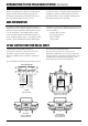
INTRODUCTION TO THE XP662 RADIO SYSTEM • Introduction Thank you for purchasing the JR XP662 6-Channel Radio System. This unit has been designed to provide the modeler with a high quality, user friendly radio system that can be depended upon for years to come. It is important that you carefully read this manual before attempting to operate your XP662 System. Please pay particular attention to Page 13, Chapter 4 Charging Your XP662 Radio System, prior to Installing.
AIRPLANE QUICK START In this manual you will find in-depth instructions that detail all the steps and procedures you should follow in order to program each of the XF662’s features. For modelers who want to get into the air fast, we have provided Quick Start. Quick Start covers the basic programming information necessary to get you airborne. Later, when you want to learn more about specific features of the XP662, turn to the appropriate page(s) in this manual for more detailed programming information.
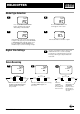
AIRPLANE QUICK START Travel Adjustment 9 10 AIL TRV ADJ. AIL TRV ADJ. +I00% +I00% ENTER ENTER INCREASE DECREASE SCROLL CHANNEL Press the SCROLL button until “TRV ADJ” appears on the screen. Press the CHANNEL button to select the channel on which you want the travel adjusted. 11 AIL TRV ADJ. INCREASE DECREASE SCROLL CHANNEL INCREASE To increase the travel, move the stick (i.e. aileron) to the right then press the INCREASE button to adjust the right travel.
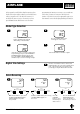
HELICOPTER QUICK START Model Type Selection 1 2 TYP TYP AC AC Press the SCROLL and INCREASE buttons simultaneously and hold while turning on the transmitter. 3 Press the SCROLL button until “TYP” appears on the screen. 4 TYP ACI 9.7V AC If “HE” appears on the screen, procede directly to Step 4. If “AC” appears, press the INCREASE or DECREASE button until “HE” appears, then press the SCROLL and INCREASE buttons simultaneously to store the model type change.
HELICOPTER QUICK START Travel Adjustment 9 10 AIL TRV ADJ. AIL TRV ADJ. +I00% +I00% ENTER ENTER Press the SCROLL button until “TRV ADJ” appears on the screen. Press the CHANNEL button to select the channel on which you want the travel adjusted. INCREASE DECREASE SCROLL CHANNEL INCREASE DECREASE SCROLL CHANNEL INCREASE To increase the travel, move the stick (i.e. aileron) to the right then press the INCREASE button to adjust the right travel.
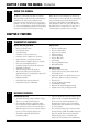
CHAPTER 1: USING THIS MANUAL • Introduction 1 USING THIS MANUAL The XP662 is a full feature introductory computer radio for airplanes and/or helicopters. This manual is divided into two main sections: airplanes and helicopters. You need only refer to the section that pertains to the type of model you are programming— e.g., if you are programming your XF662 for helicopters, follow the instructions in the helicopter section. Blank data sheets are included at the end of both sections.
CHAPTER 2: FEATURES • Introduction 2.3 SERVO FEATURES 537 Servo • An ultra-tight deadband amplifier ensures accurate neutral centering • Low-current drain 2.
CHAPTER 3: SPECIFICATIONS • Introduction 3.1 SYSTEM SPECIFICATIONS TYPE AIRPLANE SYSTEM NAME 3.2 XP662A XP662H TRANSMITTER BODY NET-XP662A NET-XP662H RECEIVER R700 R700 CHARGER NEC-221 NEC-222 AIRBORNE BATTERY 4N-600 4N-1000 SERVOS NES-537BBX4 NES-537BBX5 ACCESSORIES Mini Switch 12" Aileron Extension Servo Accessories Instruction Manual Function Guide Mini Switch 12" Aileron Extension Servo Accessories Instruction Manual Function Guide TRANSMITTER SPECIFICATIONS TYPE 3.
CHAPTER 3: SPECIFICATIONS • Introduction 3.4 RECEIVER SPECIFICATIONS TYPE 3.5 R700 FM MODEL NUMBER NER-700 TYPE 7-Channel/FM Slimline ABC & W Circuitry FREUENCY 50/72MHz SENSITIVITY (Microseconds) 5µs Minimum SELECTIVITY 8KHz/50dB WEIGHT(oz) 0.64 oz SIZE(in) (W x L x H) 1.84 x 0.98 x 0.16 RECEIVER ANTENNA 39" For All Aircraft Frequencies CHARGER SPECIFICATIONS TYPE 3.
CHAPTER 4: BATTERY CHARGING • Introduction 4.1 TRANSMITTER/RECEIVER It is imperative that you fully charge both the transmitter and the receiver battery packs prior to each day of flying. For the initial charge, leave the charger and batteries hooked up for 20–24 hours in order to fully charge both battery packs to peak capacity. For subsequent charges, leave the charger and batteries hooked up overnight (approximately 16 hours).
CHAPTER 5: TRAINER SYSTEM • Introduction 5 TRAINER SYSTEM The XP662 features a built-in trainer system. The transmitter can be used as either a master (trainer) or as a slave (trainee). The XP662 is compatible with all D.S.C. other current JR radios that have built-in trainer systems. An optional Trainer Cord (JRPA130) is needed .
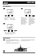
CHAPTER 1: TRANSMITTER CONTROLS • Airplane 1.1 CONTROL IDENTIFICATION AND LOCATION • Mode II ANTENNA LCD SCREEN THROTTLE TRIM ELEVATOR TRIM CARRYING HANDLE TRAINER BUTTON GEAR SWITCH ELEVATOR DUAL RATE THROTTLE/RUDDER STICK THROTTLE CUT BUTTON AUX 1/FLAP MIXING AILERON DUAL RATE AILERON/ELEVATOR STICK NECK STRAP EYELET RUDDER TRIM AILERON TRIM POWER SWITCH INPUT KEYS 1.
CHAPTER 1: TRANSMITTER CONTROLS • Airplane 1.3 RECEIVER CHANNEL ASSIGNMENT/TRANSMITTER THROTTLE ALT 1. 2. 3. 4. 5. 6. 1.4 THRO Throttle Channel AILE Aileron Channel ELEV Elevator Channel RUDD Rudder Channel GEAR Gear Channel AUX 1 Auxiliary 1 Channel (Flap) Transmitter Throttle ALT The Throttle ALT function makes the throttle stick trim active only when the throttle stick is less than half throttle. This gives easy, accurate idle adjustments without affecting the high throttle position.
CHAPTER 1: TRANSMITTER CONTROLS • Airplane 1.5 CONTROL STICK LENGTH ADJUSTMENT To adjust the control stick length, use a 2mm Allen wrench to unlock the set screw located inside the end of the control stick. Turn the set screw counterclockwise to loosen it, then turn the knurled portion of the stick to adjust the length. Counterclockwise will lengthen the stick and clockwise will shorten it. After the control stick(s) has been adjusted to suit your flying style, tighten the set screw. 1.
CHAPTER 2: CONNECTIONS • Airplane 2.1 INSTALLATION REQUIREMENTS Please read and carefully follow these suggestions. 1. For added protection, wrap the RX and the RX Ni-Cd in foam rubber that is at least 1/4” thick. 2. Run the RX antenna through the fuselage and make sure it is fully extended. Never cut or bundle your RX antenna—this will decrease range and performance. 3. Rubber servo grommets are included with your radio system and should be installed in the servo flanges.
CHAPTER 3: KEY INPUT AND DISPLAY • Airplane 3 KEY INPUT AND DISPLAY Two input keys are located at the lower right and left faceplate of the XP662 transmitter. The keys are used to access and program the transmitter. Each key can be moved up or down using your thumbs. ENTER SCROLL CHANNEL Left button up........SCROLL — Used to advance through the menus Left button down...CHANNEL — Used to advance through the channels or features in a given function INCREASE DECREASE Right button up........
CHAPTER 5: INPUT MODE AND FUNCTION • Airplane 5.1 NORMAL DISPLAY AC = FIXED WING AIRCRAFT HE = HELICOPTER When the power switch is turned on, the screen will read as shown here in the diagram. This screen is referred to as the normal display. 5.2 AC I I0.4V DIRECT TRIM ACCESS DISPLAY The Direct Trim function of the XP662 can be accessed through the use of any of the four digital trims levers (throttle, aileron, elevator, or rudder).
CHAPTER 5: INPUT MODE AND FUNCTION • Airplane 5.4 THR - REV•NORM FUNCTION MODE To enter the Function mode, turn on the transmitter. Press the MODE and CHANNEL buttons simultaneously until a beep is heard. The display will change accordingly and show the last active function. Press the MODE button to scroll down through the functions one by one as shown in the flowchart below. Once the appropriate function is selected, use the CHANNEL button to select the appropriate channel.
CHAPTER 6: FUNCTIONS (SYSTEM MODE) • Airplane 6.1 MODEL TYPE SELECTION Two types of aircraft programming are available with the XP662, airplane (AC) and helicopter (HE). When you enter the model type selection function, the current model type will appear on the screen. (The current model type being the factory preset or the last model used.) When you press the INCREASE or DECREASE button to change the model type, the new model type indicated on the screen will flash.
CHAPTER 6: FUNCTIONS (SYSTEM MODE) • Airplane 6.2 DATA RESET The data reset function allows you to reset all the programming in the selected model (1–6) to the factory settings. Before using the Data Reset function, it’s important to enter the model selection function and select the desired model number (1–6) for which you want to reprogram to the factory settings. The model selection function is described in Section 6.2.
CHAPTER 6: FUNCTIONS (SYSTEM MODE) • Airplane 6.3 DUAL RATE SWITCH SELECTION The dual rate switch position is selectable and the elevator and aileron dual rates can be combined on one switch. This allows a single switch to be used when moving from high rates for wild maneuvers to low rates for mild maneuvers. Exponential Rate (EXP) is also available for both aileron and elevator D/R SW E.
CHAPTER 6: FUNCTIONS (SYSTEM MODE) • Airplane 6.4 WING TYPE SELECTION Flaperon, V-tail, and Delta Mixing are available for specialty aircraft that require those functions. The flaperon feature mixes flaps with ailerons so the ailerons can be drooped for takeoffs and landings while still functioning fully as ailerons. V-Tail Mixing combines rudder and elevator for V-Tail operations. The Delta Wing function allows the aileron to also act as the elevator, while retaining independent use of both functions.
CHAPTER 6: FUNCTIONS (SYSTEM MODE) • Airplane 6.4 WING TYPE SELECTION (continued) To Activate Flaperon (FPR) Mixing (Wing Type Mode) FPR MIX OF ENTER INCREASE DECREASE SCROLL CHANNEL 1. In System Setup mode, press the SCROLL button until “MIX WNG” appears on the screen. OF = MIX OF ON = MIX ON 2. Press the INCREASE button to activate Flaperon Mixing. To Activate Delta-Wing (DLT) Mixing (Wing Type Mode) MIX OF ENTER INCREASE DECREASE SCROLL CHANNEL MIX 1.
CHAPTER 6: FUNCTIONS (SYSTEM MODE) • Airplane 6.5 MODEL SELECTION The XP662 has memory for six models. It can store the settings for six airplanes, six helicopters, or three airplanes and three helicopters, etc. MDL INDICATES MODEL SELECTION FUNCTION I MODEL NUMBER 11 OR 2 THROUGH 6 ENTER SCROLL CHANNEL In System Setup mode, press the SCROLL button until “MDL” appears on the screen. INCREASE DECREASE Press the INCREASE or DECREASE button to select model number 1–6.
CHAPTER 6: FUNCTIONS (SYSTEM MODE) • Airplane 6.6 MODEL NAME ENTRY The XP662 allows a three-digit name to be input for each of the six models available. The current model will be displayed in the normal display. This feature helps identify different aircraft types or model setups. Flashing character includes character to be adjusted ENTER INCREASE DECREASE SCROLL CHANNEL In System Setup mode, press the SCROLL button until “MD1” appears on the screen.
CHAPTER 6: FUNCTIONS (SYSTEM MODE) • Airplane 6.7 MODULATION SELECT The modulation select function enables your XP662 to transmit to a variety of JR receivers that are already, or may soon be, in existence. You can select from either PPM (FM), Z-PCM or S-PCM,depending on the central processing unit within your receiver to utilize existing receivers, or to upgrade your XP662 flight pack for future models.
CHAPTER 6: FUNCTIONS (SYSTEM MODE) • Airplane 6.8 FAIL-SAFE/HOLD The Fail-Safe/Hold function is available only when you use the XP662 transmitter in either of the PCM modulations: S-PCM or Z-PCM. This function is designed to help minimize damage to your airplane during a loss of signal to the receiver. The servos either assume the fail-safe presets or hold the last good signal position.
CHAPTER 6: FUNCTIONS (SYSTEM MODE) • Airplane 6.9 FAIL-SAFE/HOLD FUNCTIOn IN Z-PCM MODULATION (continued) Setting Fail-Safe/Hold Time Delay/Memory In Z-PCM Modulation ENTER INCREASE DECREASE SCROLL CHANNEL Press either the INCREASE or DECREASE buttons to select the desired time delay. 1. After accessing the Fail-Safe function, it is now time to adjust the fail-safe time presets. FST HO HO = ALL SERVOS HOLD 0.3 = 1/3 SECOND TIME DELAY 0.5 = 1/2 SECOND TIME DELAY 1.0 = 1 SECOND TIME DELAY HOLD 0.
CHAPTER 6: FUNCTIONS (SYSTEM MODE) • Airplane 6.10 FAIL-SAFE/HOLD FUNCTION IN S-PCM MODULATION Hold Function (S-PCM) The Hold function is automatically activated when the radio is turned on and in the S-PCM modulation. This function stops (or holds) the servos in the positions they were in just prior to the interference. Therefore, your aircraft maintains the position held immediately before the interference was experienced.
CHAPTER 6: FUNCTIONS (SYSTEM MODE) • Airplane 6.10 FAIL-SAFE/HOLD FUNCTION IN S-PCM MODULATION (continued) Activating Servo Fail-Safe Presets by Channel (S-PCM) 1. Press the SCROLL and INCREASE buttons simultaneously and hold. 2. Turn on the transmitter to enter the system mode. 3. Press the SCROLL button until “FS1” appears on the screen. The #1 on the screen refers to the specific channel (1-6) to be adjusted. 4.
CHAPTER 7: FUNCTIONS (FUNCTION MODE) • Airplane 7.1 SERVO REVERSING Servo reversing is a very convenient function used in the setup of a new aircraft. It is used to change the direction of servo rotation in relation to the THR corresponding stick movement. Servo reversing is available for all six channels.
CHAPTER 7: FUNCTIONS (FUNCTION MODE) • Airplane 7.2 DUAL RATE Dual rate is available for the aileron and elevator channels. The purpose of this function is to allow for in-flight selection of two preset servo travels for each of these channels. The amount of travel is adjustable from 0-125%. The factory settings for both switch positions (0 and 1) is 100%. Either position may be selected as the low or high rate by placing the switches in the desired position and adjusting the value for that position.
CHAPTER 7: FUNCTIONS (FUNCTION MODE) • Airplane 7.3 EXPONENTIAL Programmable exponential adjustments are offered on the aileron and elevator channels of your XP662 system. Exponential is a function that allows you to tailor the response rate of the controls as compared to the stick inputs. The purpose of exponential is to reduce the sensitivity in the middle portion of stick movement, while still allowing full travel at the end of the stick movement.
CHAPTER 7: FUNCTIONS (FUNCTION MODE) • Airplane 7.4 SUB-TRIM Sub-trim is an electronic trim that is available for each of the six channels. Sub-trim is particularly useful as it allows the mechanical trim levers to be returned to their neutral positions by adjusting/ changing the servo’s neutral position electronically, without the need to mechanically adjust the specific control linkage. This allows the same mechanical trim lever settings between the four models you can control with this radio system.
CHAPTER 7: FUNCTIONS (FUNCTION MODE) • Airplane 7.5 TRAVEL ADJUSTMENT The amount of servo travel is adjustable for each direction for each of the six channels individually. The adjustment range is from 0% to 150%. Travel adjustment is factory set at 100% for all channels. The travel adjustment value displayed on the screen depends on the position of the stick or switch (e.g., flap switch, gear switch).
CHAPTER 7: FUNCTIONS (FUNCTION MODE) • Airplane 7.6 AILERON-TO-RUDDER MIXING On some types of aircraft, it is desirable to mix aileron and rudder to make coordinated turns. The XP662 allows the mixing of aileron-to-rudder and allows you to adjust the amount and direction of MIX + A- R 0% mixing. The aileron-to-rudder mixing can be left on all the time, or it can be turned off with the selection of one of three switches.
CHAPTER 7: FUNCTIONS (FUNCTION MODE) • Airplane 7.6 AILERON-TO-RUDDER MIXING (continued) Aileron-to-Rudder Mixing Switch Selection MIX ARS INDICATES THE AILERON TO RUDDER MIXING SWITCH FUNCTION ONN MIXING SWITCH ON = MIXING IS ALWAYS ACTIVATED S = GEAR SWITCH A = AILERON DUAL RATE SWITCH F1 = FLAP SWITCH ENTER SCROLL CHANNEL INCREASE DECREASE Press the CHANNEL button until “MIX-ARS” appears on the screen.
CHAPTER 7: FUNCTIONS (FUNCTION MODE) • Airplane 7.7 ELEVATOR-TO-FLAP MIXING Elevator-to-flap mixing is commonly used to quicken the pitching rate of an aircraft. This is very popular in fun fly airplanes because it allows tighter loops. MIX + E-F Normally, with up elevator the flaps go down, while down elevator makes the flaps go up.
CHAPTER 7: FUNCTIONS (FUNCTION MODE) • Airplane 7.7 ELEVATOR-TO-FLAP MIXING (continued) Elevator-to-Flap Mixing Switch Selection MIX EFS INDICATES THE ELEVATOR-TO-FLAP MIXING SWITCH FUNCTION ONN MIXING SWITCH ON = MIXING IS ALWAYS ON S = LANDING GEAR SWITCH E = ELEVATOR DUAL RATE F0 = FLAP SWITCH ENTER SCROLL CHANNEL INCREASE DECREASE Press the CHANNEL button until “EFS” appears on the screen. Press the INCREASE or DECREASE button until the desired switch designation appers on the screen.
CHAPTER 7: FUNCTIONS (FUNCTION MODE) • Airplane 7.8 DIFFERENTIAL Aileron differential is used to correct roll to yaw coupling and adverse yaw characteristics. In order to activate differential, the flaperon wing type must have been selected in the system mode (see Section 6.4).
CHAPTER 7: FUNCTIONS (FUNCTION MODE) • Airplane 7.9 FLAP-TO-ELEVATOR OFFSET TRIM When the flaps are deployed, most airplanes exhibit pitching tendencies (most pitch nose up). Elevator offset trim is designed to prevent this pitching. Flap to elevator offset trim automatically retrims the elevator to a preset value when the flap switch is activated. OFFSET F-E Note: Flap-to-elevator offset trim is also useful as a dual elevator trim even for airplanes without flaps.
CHAPTER 7: FUNCTIONS (FUNCTION MODE) • Airplane 7.10 PROGRAMMABLE MIXING (A,B,C) The XP662 in aircraft mode offers three programmable mixes to be used for a number of different purposes. The functions allow mixing any one channel to any other channel. The mix can remain ON at all times, or be switched OFF in flight using a number of different switches. (Refer to Chart A). Each channel is identified by channel numbers 1-6 (i.e., 2 = aileron, 4 = rudder, etc.
CHAPTER 7: FUNCTIONS (FUNCTION MODE) • Airplane 7.10 PROGRAMMABLE MIXING (A,B,C) (continued) Assigning Channels ENTER MIX INCREASE DECREASE SCROLL CHANNEL Press the CHANNEL button until “MIX A ch” appears. Press INCREASE to select Master Channel desired. 1. Press the channel button twice until “MIX A CH” appears on the screen. 2. Press the (+) button to select the desired Master Channel (1-6). A CH 24 Press DECREASE to select Slave Channel desired. MASTER CHANNEL SLAVE CHANNEL 3.
CHAPTER 7: FUNCTIONS (FUNCTION MODE) • Airplane 7.10 PROGRAMMABLE MIXING (A,B,C) (continued) Mixing Value Adjustment CURRENT MIX ENTER INCREASE DECREASE SCROLL CHANNEL MIX Press the CHANNEL button once until “MIX A” and MIX value % appears A24 % 0 Press either the INCREASE or DECREASE buttons to increase/decrease mixing value. 1. Press the CHANNEL button once until “MIX A” appears, with the mixing value located at the bottom of the screen. 2.
CHAPTER 8: DATA SHEET • Airplane 8 Data Sheet Modulation SPCM • ZPCM • PPM (FM) Model Number _____________________ Model Name ______________________ CHANNELS THRO (1) AIL (2) ELE (3) RUDD (4) GER(5) AUX1 (6) NORM • REV NORM • REV NORM • REV NORM • REV NORM • REV NORM • rev REVERSE SW SUB-TRIM TRAVEL ADJUST + % + % + % + % + % + (TRV ADJ.
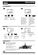
CHAPTER 1: TRANSMITTER CONTROLS • Helicopter 1.1 CONTROL IDENTIFICATION AND LOCATION • Mode II ANTENNA LCD SCREEN THROTTLE TRIM ELEVATOR TRIM CARRYING HANDLE THROTTLE CUT BUTTON TRAINER BUTTON GEAR SWITCH AUX 1/FLAP MIXING AILERON DUAL RATE ELEVATOR DUAL RATE AILERON/ELEVATOR STICK THROTTLE/RUDDER STICK NECK STRAP EYELET RUDDER TRIM AILERON TRIM POWER SWITCH INPUT KEYS 1.2 RECEIVER CHANNEL ASSIGNMENT/TRANSMITTER THROTTLE ALT 1. 2. 3. 4. 5. 6.
CHAPTER 1: TRANSMITTER CONTROLS • Helicopter 1.3 TRANSMITTER REAR Note: Your transmitter has a 5-year lithium battery to protect your pre-programmed data against main transmitter battery failure. If you system reads 0.0 volts, or has an unfamiliar display (service mode) or your data resets to the factory defaults, return your transmitter to Horizon Service Center (see page 85) for lithium battery replacement.
CHAPTER 1: TRANSMITTER CONTROLS • Helicopter 1.4 CONTROL STICK LENGTH ADJUSTMENT To adjust the control stick length, use a 2mm Allen wrench to unlock the set screw located inside the end of the control stick. Turn the set screw counterclockwise to loosen it, then turn the knurled portion of the stick to adjust the length. Counterclockwise will lengthen the stick and clockwise will shorten it. After the control stick(s) has been adjusted to suit your flying style, tighten the set screw back. 1.
CHAPTER 2: CONNECTIONS • Helicopter 2.1 INSTALLATION REQUIREMENTS Please read and carefully follow these suggestions. 1. For added protection, wrap the RX and the RX Ni-Cd in foam rubber that is at least 1/4” thick. 2. Run the RX antenna through the fuselage and make sure it is fully extended. Never cut or bundle your RX antenna—this will decrease range and performance. 3. Rubber servo grommets are included with your radio system and should be installed in the servo flanges.
CHAPTER 3: KEY INPUT AND DISPLAY • Helicopter 3 KEY INPUT AND DISPLAY Two input keys are located at the lower right and left faceplate of the XP662 transmitter. The keys are used to access and program the transmitter. Each key can be moved up or down using your thumbs. ENTER SCROLL CHANNEL Left button up........SCROLL — Used to advance through the menus Left button down...CHANNEL — Used to advance through the channels or features in a given function INCREASE DECREASE Right button up........
CHAPTER 5: INPUT MODE AND FUNCTION • Helicopter AC = FIXED WING AIRCRAFT HE = HELICOPTER 5.1 NORMAL DISPLAY When the power switch is turned on, the screen will read as shown here in the diagram. This screen is referred to as the normal display. 5.2 SYSTEM MODE To enter the System mode, press the SCROLL and INCREASE buttons simultaneously while you turn on the transmitter. You can now select any of eight system mode functions shown here in the flow chart.
CHAPTER 5: INPUT MODE AND FUNCTION • Helicopter 5.3 THR FUNCTION MODE - REV•NORM To enter the Function mode, turn on the transmitter. Press the SCROLL and INCREASE buttons simultaneously until a beep is heard. The display will change accordingly and show the last active function. Press the SCROLL button to scroll down through the functions one by one as shown in the flowchart at right. Once the appropriate function is selected, use the CHANNEL button to select the appropriate channel.
CHAPTER 6: FUNCTIONS (SYSTEM MODE) • Helicopter 6.1 MODEL TYPE SELECTION Two types of aircraft programming are available with the XP662, airplane (AC) and helicopter (HE). When you enter the model type selection function, the current model type will appear on the screen. (The current model type being the factory preset or the last model used.) When you press the increase or decrease button to change the model type, the new model type indicated on the screen will flash.
CHAPTER 6: FUNCTIONS (SYSTEM MODE) • Helicopter 6.2 DATA RESET The Data Reset function allows you to reset all the programming in the selected model (1-6) to the factory settings. Before using the data reset function it is important to enter the Model Selection function RST HE and check that the current model number (1-6) indicated is the model that you want to reprogram to the factory settings. The model selection function is described in Section 6.5.
CHAPTER 6: FUNCTIONS (SYSTEM MODE) • Helicopter 6.3 DUAL RATE SWITCH SELECTION The dual rate switch position is selectable and the elevator and aileron dual rates can be combined on one switch. This allows a single switch to be used when moving from high rates for wild maneuvers to low rates for mild maneuvers. Exponential Rate (EXP) is also available for both aileron and elevator and D/R SW E.
CHAPTER 6: FUNCTIONS (SYSTEM MODE) • Helicopter 6.4 GEAR/GYRO SWITCH SELECTION The XP662 gear/gyro switch selection function enables the dual rate values of the gyro to be combined with one of four switches (flight mode, throttle hold, aileron dual rate, elevator dual rate). This feature is for use with gyros that offer a dual rate sensitivity adjustment, such as the JR G460T Piezo GER Gyro (JRPG460T).
CHAPTER 6: FUNCTIONS (SYSTEM MODE) • Helicopter 6.5 MODEL SELECTION The XP662 has memory for six models. It can store the settings for six airplanes, six helicopters or three airplanes and three helicopters, etc. MDL INDICATES MODEL SELECTION FUNCTION I THROUGH 6 MODEL NUMBER 1 OR 2 ENTER SCROLL CHANNEL INCREASE DECREASE Press the SCROLL button until “MDL” appears on the screen. Press the INCREASE or DECREASE buttons to select model number 1 through 6. Accessing the Model Selection Function 1.
CHAPTER 6: FUNCTIONS (SYSTEM MODE) • Helicopter 6.6 MODEL NAME ENTRY The XP662 allows a 3-digit name to be input for each of the six models available. The current model will be displayed in the normal display. This feature is useful to help identifydifferent aircraft types, or model setups. FLASHING INDICATES CHARACTER TO BE ADJUSTED ENTER SCROLL CHANNEL In System Setup mode, press the SCROLL button until “MD1” appears on the screen.
CHAPTER 6: FUNCTIONS (SYSTEM MODE) • Helicopter MODULATION SELECT 6.7 The modulation select function enables your XP662 to transmit to a variety of JR receivers that are already, or may soon be, in existence. You can select from either PPM (FM), Z-PCM or S-PCM,depending on the central processing unit within your receiver to utilize existing receivers, or to upgrade your XP662 flight pack for future models.
CHAPTER 6: FUNCTIONS (SYSTEM MODE) • Helicopter 6.8 FAIL-SAFE/HOLD The Fail-Safe/Hold function is available only when you use the XP662 transmitter in either of the PCM modulations: S-PCM or Z-PCM. This function is designed to help minimize damage to your airplane during a loss of signal to the receiver. The servos either assume the fail-safe presets or hold the last good signal position.
CHAPTER 6: FUNCTIONS (SYSTEM MODE) • Helicopter 6.9 FAIL-SAFE/HOLD FUNCTION IN Z-PCM MODULATION (continued) Setting Fail-Safe/Hold Time Delay/Memory In Z-PCM Modulation 1. After accessing the Fail-Safe function, it is now time to adjust the fail-safe time presets. ENTER INCREASE DECREASE SCROLL CHANNEL Press either the INCREASE or DECREASE buttons to select the desired time delay. 2. Select among the three time delays (.3, .5, or 1.
CHAPTER 6: FUNCTIONS (SYSTEM MODE) • Helicopter 6.10 FAIL-SAFE/HOLD MEMORY IN S-PCM MODULATION Hold Function (S-PCM) The Hold function is automatically activated when the radio is turned on and in the S-PCM modulation. This function stops (or holds) the servos in the positions they were in just prior to the interference. Therefore, your aircraft maintains the position held immediately before the interference was experienced.
CHAPTER 6: FUNCTIONS (SYSTEM MODE) • Helicopter 6.10 FAIL-SAFE/HOLD MEMORY IN S-PCM MODULATION (continued) Activating Servo Fail-Safe Presets by Channel (S-PCM) 1. Press the SCROLL and INCREASE buttons simultaneously and hold. 2. Turn on the transmitter to enter the system mode. 3. Press the SCROLL button until “FS1” appears on the screen. The #1 on the screen refers to the specific channel (1-6) to be adjusted.
CHAPTER 7: FUNCTIONS (FUNCTION MODE) • Helicopter 7.1 SERVO REVERSING Servo reversing is a very convenient function used in the setup of a new aircraft. It is used to change the direction of servo rotation in relation to the corresponding stick movement. Servo reversing is available for all six channels.
CHAPTER 7: FUNCTIONS (FUNCTION MODE) • Helicopter 7.2 DUAL RATE Dual rate is available for the aileron and elevator Different types of maneuvers require varying channels. The purpose of this function is to allow for amounts of control movements. Snap rolls require in-flight selection of two preset servo travels for each large control movements, while smooth maneuvers of these channels. The amount of travel is adjustable like long slow rolls are best performed with smaller from 0-125%.
CHAPTER 7: FUNCTIONS (FUNCTION MODE) • Helicopter 7.3 EXPONENTIAL Programmable exponential adjustments are offered on the aileron and elevator channels of your XP662 system. Exponential is a function that allows you to tailor the response rate of the controls as compared to the stick inputs. The purpose of exponential is to reduce the sensitivity in the middle portion of stick movement, while still allowing full travel at the end of the stick movement.
CHAPTER 7: FUNCTIONS (FUNCTION MODE) • Helicopter 7.4 SUB-TRIM Sub-trim is an electronic trim that is available for each of the six channels. Sub-trim is particularly useful as it allows the mechanical trim levers to be returned to their neutral positions by adjusting /changing the servo’s neutral position electronically, without the need to mechanically adjust the specific control linkage. This allows the same mechanical trim lever settings between the five models you can control with this radio system.
CHAPTER 7: FUNCTIONS (FUNCTION MODE) • Helicopter 7.5 TRAVEL ADJUSTMENT The amount of servo travel is adjustable for each direction for each of the 6 channels individually. The adjustment range is from 0% to 150%. Travel adjustment is factory set at 100% for all channels. The travel adjustment value displayed on the screen depends on the position of the stick or switch (e.g., flap switch, gear switch).
CHAPTER 7: FUNCTIONS (FUNCTION MODE) • Helicopter 7.6 THROTTLE HOLD The throttle hold function enables the throttle servo to be held in a specific location, while allowing the collective pitch servo to move independently with the throttle stick. The purpose of this function is for practicing autorotation landings with the helicopter’s engine at idle. When the throttle hold switch is H LD – changed from off to activated, there will be a third adjustable pitch curve added to the pitch curve function.
CHAPTER 7: FUNCTIONS (FUNCTION MODE) • Helicopter PITCH CURVE The XP652 offers three separate pitch curves with three adjustable reference points per curve. This function allocates a separate pitch curve setting during Normal, Stunt, and Throttle Hold modes to maximize flight performance. Once the pitch curves are established, each can be activated in flight using the two-position flight mode switch and the throttle hold switch.
CHAPTER 7: FUNCTIONS (FUNCTION MODE) • Helicopter 7.8 THROTTLE CURVE Adjustment of the throttle curve is very similar to the pitch curve adjustment described in the preceding section. A thorough understanding of the pitch curve section will make the throttle curve section easier to understand. The two throttle curves are activated by the flight mode switch located on the top left rear corner of the transmitter.
CHAPTER 7: FUNCTIONS (FUNCTION MODE) • Helicopter 7.9 REVOLUTION MIXING (Non-Heading Lock Gyros Only) The Revolution Mixing function combines tail rotor input with the throttle/collective function to counteract the torque created by the main rotor blades. When properly adjusted, the helicopter will climb and descend without a tendency to yaw in either direction. Revolution mixing is for use with non heading lock gyros only.
CHAPTER 7: FUNCTIONS (FUNCTION MODE) • Helicopter 7.10 PROGRAMMABLE MIXING (A) The XP662 in Helicopter mode offers one (1) programmable mix to be used for a number of different purposes. The functions allow mixing any one channel to any other channel. The mix can remain on at all times or be switched off in flight using a number of different switches. (Refer to Chart A). Each channel is identified by channel numbers 1-6 (i.e., 2 = aileron, 4 = rudder, etc.
CHAPTER 7: FUNCTIONS (FUNCTION MODE) • Helicopter 6.20 PROGRAMMABLE MIXING (A) (continued) Assigning Channels ENTER INCREASE DECREASE SCROLL CHANNEL Press the CHANNEL button until “MIX A” Ch appears. Press DECREASE to select Slave Channel desired. MIX 32 Press INCREASE to select Master Channel desired. 1. Press the CHANNEL button twice until “MIX A CH” appears on the screen. 2. Press the INCREASE button to select the desired “Master Channel” (1-6). A CH MASTER CHANNEL SLAVE CHANNEL 3.
CHAPTER 7: FUNCTIONS (FUNCTION MODE) • Helicopter 7.10 PROGRAMMABLE MIXING (A) (continued) Mixing Value Adjustment ENTER INCREASE DECREASE SCROLL CHANNEL Press the CHANNEL button once until “MIX A” and value % appears MIX 0 Press either the INCREASE or DECREASE buttons to increase/decrease mixing value. 1. Press the Channel button once until “Mix A” appears, with the mixing value located at the bottom of the screen. 2.
CHAPTER 7: FUNCTIONS (FUNCTION MODE) • Helicopter 7.11 CCPM SWASHPLATE MIXING The CCPM Swashplate Mixing function (Cyclic Collective Pitch Mixing) of the XP662 system is designed to allow the XP662 to be used in model helicopters that utilize a 120° CCPM-type swashplate control system. CCPM is a type of pitch mixing where the three servos are connected directly to the swashplate of the helicopter and physically move both in unison and independently for all changes in pitch/ cyclic.
CHAPTER 7: FUNCTIONS (FUNCTION MODE) • Helicopter 7.11 CCPM SWASHPLATE MIXING (continued) Accessing the CCPM Swashplate Mixing Function 1. Turn on the transmitter. 2. Press the SCROLL and INCREASE buttons simultaneously to enter the function mode. 3. Press the SCROLL button until “CCP” appears on the screen. 4. Press the INCREASE button once to activate the CCPM Swashplate Mix function. The screen will then move to the “CP2” screen, indicating that the CCPM function is now on. 7.12 5.
CHAPTER 7: FUNCTIONS (FUNCTION MODE) • Helicopter 7.13 HOW 120 CCPM WORKS As mentioned previously, 120° Three-Servo CCPM relies on the radio’s special CCPM swashplate mixing, rather than a conventional mechanical mixer that is utilized to achieve the same results. The radio’s 120° Three-Servo CCPM function automatically mixes the three servos to provide the correct mixing inputs for aileron (roll), elevator (pitch), and collective.
CHAPTER 7: FUNCTIONS (FUNCTION MODE) • Helicopter 7.13 HOW 120 CCPM WORKS (continued) 120 Three-Servo CCPM Swashplate Mixing The JR 120° CCPM or Cyclic/Collective Pitch Mixing system offers the user a control system that can accomplish the same control inputs as the One-Servo Standard system, but with increased precision and reduced complexity. As with the One-Servo system, the JR CCPM system utilizes three servos for the three main controls: aileron (roll), elevator (pitch) and collective.
CHAPTER 8: DATA SHEET • Helicopter 8 Data Sheet Modulation S-PCM • Z-PCM • PPM (FM) Model Number ______________________ Model Name ________________________ CHANNEL THR (1) AIL (2) ELE (3) RUD (4) GER (5) PITCH (6) NORM • REV NORM • REV NORM • REV NORM • REV NORM • REV NORM • REV * REVERSE SW SUB-TRIM TRAVEL ADJUST + % + % + % + % + % + % (TRV ADJ.
IMPORTANT INFORMATION 1 GENERAL NOTES Radio controlled models are a great source of pleasure. Unfortunately, they can also pose a potential hazard if not maintained and operated properly. It is imperative that you install your radio control system correctly. Additionally, your level of piloting competency must be high enough to ensure that you are able to control your aircraft under all conditions.
IMPORTANT INFORMATION 3 WARRANTY COVERAGE Your new equipment is warranted to the original purchaser against manufacturer defects in material and workmanship for one year from the date of purchase. During this period, Horizon Service Center will repair or replace, at our discretion, any component that is found to be factory defective at no cost to the purchaser. This warranty is limited to the original purchaser of the unit and is not transferable.
IMPORTANT INFORMATION 5 FREQUENCY CHART 72MHz requires no special license to operate. 50MHz requires the operator to have an FCC amateur radio license (Ham). 72MHz CH.NO. FREQUENCY 72MHz CH.NO. FREQUENCY CH.NO. FREQUENCY 15 72.090 36 72.510 00 50.800 16 72.110 37 72.530 01 50.820 17 72.130 38 72.550 02 50.840 18 72.150 39 72.570 03 50.860 19 72.170 40 72.590 04 50.880 20 72.190 41 72.610 05 50.900 21 72.210 42 72.630 06 50.920 22 72.230 43 72.
Distributed exclusively by Horizon Hobby, Inc. Champaign, IL 61822 www.horizonhobby.com © 2002 Horizon Hobby, Inc.