
User Manual

Thank you for choosing the JR Racing brand.
Your satisfaction is our number one priority. With
this in mind, we have produced this product to be
of the highest quality, performance and reliability.
We hope it provides you with hours of enjoyment
in your next RC project.
• High-power FET control with proportional
forward and reverse
• High-frequency design delivers smooth
acceleration
• Automatic Thermal Overload Protection
prevents damage from excessive current or
short circuits
• Prewired with Tamiya battery plug, bullet-style
motor connectors, and universal receiver plug
that fit JR, Hitec, Airtronics Z, Futaba and
new KO radios
• Designed to operate with stock to mild
modified motors (15 turns or higher)
• One-touch programming makes setup a breeze
Operation: ...... Proportional forward, proportional
reverse with brake
Input Voltage: ..................... 6-cell (7.2 volts) or
7-cell (8.4 volts) DC
Peak Current: .................................... 640 amps
Continuous Current: ........................ 160 amps
Full-On Resistance: .............. 0.00175 ohms x2
Frequency: ........................................... 1500 Hz
BEC output: ...................... 6 VDC, 1 amp max.
Overload Protection: ........................... Thermal
Dimensions: ....................... 1.45" x 1.71" x 0.89"
(36mm x 43mm x 22 mm)
Weight: ................................................... 1.92 oz
Note: Be sure all wiring connections can
be reached prior to mounting.
Mount the SC-1 ESC in the location specified
by your vehicles instruction manual. Use the
double-sided foam tape (included) to secure the
speed control in position and to secure the side
of the switch to a convenient location on the
chassis or shock tower.
Note: The SC-1 uses the motor battery to
supply power to the receiver through the
servo wires. There is no need for a
separate receiver battery.
• See your radio’s instruction manual for proper
connection. Typically, channel 2 is used to
control the throttle.
• There are three wires involved in the universal
receiver connector. It is directly compatible
with JR, Hitec, Airtronics Z, Futaba and new
KO systems.
• Older Airtronics or KO radio systems must use
a modified wiring order:
1. The positive (red) and negative (brown) wires
must be reversed to operate with these radio
systems. To remove the wires from the plug
use a small jewelers screwdriver to pry up the
plastic tab associated with each wire. Gently
slide the brown wire out of the plug. Repeat
on the red wire and replace in the opposite
positions.
2. Install the plug referencing the wire colors on
the steering servo for proper polarity.
3. Install the plug. Reference the wire colors on
the steering servo for proper polarity.
If the motor (15 turns or more) you are using
does not have three capacitors already attached,
you must install them. Check with your local
hobby shop for more information. The supplied
monolithic capacitors help prevent motor noise,
which lessens radio glitches.
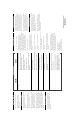
1. Using a small file, scuff up
an area on the motor can
between the positive and
negative tabs (see Figure 2).
2. Take one of the capacitors
and solder one wire to the
positive motor tab with the
other wire positioned over
the scuffed area on the
motor housing (see Figure 3).
3. Use another capacitor and
solder one wire to the
negative motor tab with the
other wire positioned over
the scuffed area as well.
4. Solder both wires to the
motor housing (see
Figure 4). A high-wattage
soldering iron may be
necessary.
5. Solder the third capacitor
from the positive to the
negative motor tabs (see
Figure 5).
6. Use side cutters to remove
excess capacitor wires.
Some forward-only ESCs require a Shottky
diode attached to the motor for noise
suppression. Be certain there is not a diode
attached to the motor when using the SC-1 or
any other reversing electronic speed control.
If your motor has pre-attached male bullet
connectors, press the red motor wire into the
plug that is wired to the positive motor terminal.
The black wire is connected in the same manner
to the negative motor tab (see Figure 6).
If your motor does not have male bullet
connectors, you may purchase a Motor
Connector Wire (DLR1055) from your
local hobby shop .
Caution: To detour
glitches caused by
RF (radio frequency)
noise, route all wires
and the receiver antenna
away from motor leads.
Secure with tie wraps
(not included).
The SC-1 comes prewired with a Tamiya-style
connector that is compatible with most battery
packs. Use either a 6-cell (7.2-volt) or 7-cell
(8.4-volt) Sub-C size battery pack.
1. Be sure the On/Off switch is in the Off
position.
2. Connect a fully charged battery pack to the
speed control’s battery connector.
Note: Refer to the radio instructions for
specific information on transmitter setup.
1. Set the Throttle Reversing switch to the
NORMAL position. (This may need to be
reversed on some brands of radios).
2. Set the Throttle Trim to the CENTER
position.
3. Set the Throttle Exponential (if applicable)
to MINIMUM or ZERO.
Features
Mounting the Speed Control
Wiring the Receiver
Motor Capacitors
Adjusting the Transmitter
Connecting the Battery
Specifications
Figure 2
Figure 5
Figure 6
Black Wire
(-) Negative
Red Wire
(+) Positive
Figure 3
Figure 4
Connecting the Motor Wires
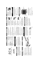
Diagram
Instruction Manual
SC-1
Figure 1
CONNECT ESC
TO CH. 2
POWER
SWITCH
TAMIYA 7.2V
CONNECTOR
SC-1
MOTOR
+
BATTERY PACK
7.2–8.4V
STEERING
SERVO
--
--
+
--
+
2-COLOR
LED
HEAT
SINKS
SETUP
BUTTON
Motor Capacitors
SC
-
1
Electronic Speed Control (ESC)
with Reverse
Connecting the Motor Wires