MARINE VHF RADIOTELEPHONE Instruction Manual 7ZPJD0714
.
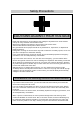
Safety Precautions CAUTIONS AGAINST HIGH VOLTAGE Radio and radar devices are operated by high voltages of anywhere from a few hundred volts up to many hundreds of thousands of volts. Observe the following precautions to prevent the risk of electric shock. Avoid contact with the internal parts of these devices. Only specialized service people should do any maintenance, inspections, or adjustments inside the devices.
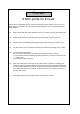
First aid ☆Note points for first aid Unless there is impending danger, leave the electrocution victim where he or she is, then begin artificial respiration. Once you begin artificial respiration, you must continue without losing rhythm. (1) Make contact with the victim cautiously, there is a risk that you may get electrocuted. (2) Switch off the machinery and then move the victim away slowly if you must. (3) Inform someone immediately (a hospital or doctor, dial emergency numbers, etc.).
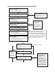
Flow of Cardiopulmonary Resuscitation (CPR) A person is collapsing. A person - Secure the safety is of the surrounding area. - Prevent secondary collapsin disasters. Check for response. - Call while tapping the shoulder. Listen to the appeal of the injured or ill person and give the necessary first-aid treatment. Responding Not responding Ask for help. - Make an emergency call. - Ask to bring an AED. Open the airway. - Check for breathing.
Specific Procedures for Cardiopulmonary Resuscitation (CPR) 1. Check the scene for safety to prevent secondary disasters a) Do not touch the injured or ill person in panic when an accident has occurred. (Doing so may cause electric shock to the first-aiders.) b) Do not panic and be sure to turn off the power. Then, gently move the injured or ill person to a safe place away from the electrical circuit. Are you OK? 2.
. Give 2 rescue breaths (omittable) a) If opening the airway does not cause the injured or ill person to begin to breathe normally, give rescue breaths. b) If there is a fear of infection because the injured or ill person has an intraoral injury, you are hesitant about giving mouth-to-mouth resuscitation, or getting and preparing the mouthpiece for rescue breathing takes too long, omit rescue breathing and perform chest compressions.
9. When to stop cardiopulmonary resuscitation (CPR) a) When the injured or ill person has been handed over to the emergency services b) When the injured or ill person has started moaning or breathing normally, lay him/her on his/her side in a recovery position and wait for the arrival of emergency services. 10. Arrival and preparation of an AED a) Place the AED at an easy-to-use position. If there are multiple first-aiders, continue CPR until the AED becomes ready. b) Turn on the power to the AED unit.
13. Electric shock (defibrillation) a) If the AED determines that electric shock is needed, the voice prompt saying, "Shock is needed" is issued and charging starts automatically. b) When charging is completed, the voice prompt saying, "Press the shock button" is issued and the shock button flashes. c) The first-aider must get away from the injured or ill person, make sure that no one is touching him/her, and then press the shock button.
Preface Thank you for purchasing JRC's JHS-800S Marine VHF Radiotelephone. This radiotelephone can be used as a Global Maritime Distress and Safety System (GMDSS) radio device, compliant with international regulations, that provides emergency communications and standard communications capabilities for small and large ships. ● ● Please read this instruction manual thoroughly before using the equipment. Please keep this manual available for future reference.
Before Operation Concerning the symbols This manual uses the following symbols to explain correct operation and to prevent injury or damage to property. The symbols and descriptions are as follows. Understand them before proceeding with this manual. WARNING Indicates a warning that, if ignored, may result in serious injury or even death. CAUTION Indicates a caution that, if ignored, may result in injury or damage to property.
About Warning Labels There is warning labels on the main unit (JHS-800S) and the power supply unit (NBD980). Do not remove, damage, or alter the warning labels.
Handling precaution WARNING Do not open the equipment to inspect or repair it. Inspection or repairs by anyone other than a specialized technician may result in fire, electrical shock, or malfunction. If internal inspection or repair is necessary, contact our service center or agents. Do not disassemble or customize this unit. Doing so may cause fire, electrical shock, or malfunction. Do not get this equipment wet or spill any liquids on or near this equipment.
CAUTION Do not use this equipment for anything other than specified. Doing so may cause failure or malfunction. Do not install this equipment in a place near water or in one with excessive humidity, steam, dust or soot. Doing so may cause fire, electric shock, or malfunction. Do not test the distress alert as doing so will inconvenience local shipping and Rescue Centers. Do NOT turn off the power of the equipment when at sea because the SOLAS Convention requires keeping CH16 watch at all times.
CAUTION When sending a drobose call, do NOT press the DISTRESS button. Doing so may cause a false distress alert. (Drobose calls can be sent via [Call] button displayed on the screen.) A distress acknowledgement or a distress relay call can be transmitted from a received distress message stored in the log, but when sending such a kind of call, follow the instructions of the ship's captain or officer in charge.
DISTRESS ALERTS Sending a Distress Alert CAUTION When sending a distress alert, follow the instructions of the ship's captain or officer in charge. 11.. Open the protective cover on the DISTRESS button for the JHS-800S Marine VHF radiotelephone or NCM-980 Controller. 22.. Press and hold the DISTRESS button for at least 3 seconds until the countdown is complete.
Note If time permits, enter the nature of the distress as follows, just before sending the distress alert. (For more details, see 4.4.5.2.) 1) On the status display, touch the [DIST-E] button. 2) On the screen at right, touch the [EDIT]→ [NATURE] buttons and then select the nature of distress. 3) Touch the [✓] button. The nature of distress is set. If the position and time are not displayed automatically, select the [EDIT]→[POS UTC] buttons and input them manually.
Receiving a Distress Alert WARNING If a distress alert is received, make sure to inform the ship's captain or officer in charge. Doing so may save the lives of the crews and passengers on the ship in distress. 11.. When a distress alert is received, the information such as the ID number of the ship in distress and the stage of the distress event are displayed. If the equipment is not used, i.e.
Equipment exterior ● JHS-800S Marine VHF Radiotelephone/ NQW-980 Handset ● NCM-980 Controller/ NQW-980 Handset xvii
● NQE-1845 Handset Connector Box Waterproofed flush mount type (for wing console) ● NQE-1846 Handset Connector Box Waterproofed wing installation type ● NQE-1847B Handset Connector Box ● NBD-965 AC/DC Power Unit ● RP-D10 Printer Indoor flush mount type ● xviii NCH-3210 Distress Message Controller
● NVS-423R/823R External Speaker ● BTR-155 Wireless speaker microphone xix
Contents Preface ................................................................................viii Before operation ................................................................ ix Handling precaution .......................................................... xi DISTRESS ALERTS ...........................................................xiv Equipment exterior ........................................................ xvii Glossary of terms ..........................................................
4.3 Basic DSC operations ....................................................................................................... 4-16 4.3.1 Routine calls to an individual station .......................................................................... 4-16 4.3.2 Receiving routine individual calls ............................................................................... 4-18 4.3.3 Routine group calls ..............................................................................................
5.5.3 Medical/Neutral use setting for urgency calls ............................................................. 5-12 5.5.4 Expanded MMSI registration ...................................................................................... 5-13 5.5.5 Registering the ship's group ID ................................................................................... 5-13 5.5.6 Setting the inactivity timeout timer .............................................................................. 5-14 5.
Glossary of terms This section contains general and DSC terms related to this equipment. ● General terms AIS Automatic Identification System Equipment that transmits a ship's Maritime Mobile Service Identity number, ship name, ship position, speed, orientation, and other information to and from other ships.
SAR Convention International Convention on Maritime Search and Rescue SOLAS Convention The international convention applied to all ships engaged on international voyages. A safety certificate is issued if the conditions of this convention are satisfied. SQL (Squelch) A function that acts to suppress the audio output of a receiver in the absence of a sufficient radio strength signal.
Nature of Distress Message code indicating type of distress when a distress call is issued. It contains types as below. ・ FIRE ...................... Fire, explosion ・ FLOODING ............ Flooding ・ COLLISION ............. Collision ・ GROUNDING .......... Grounding ・ LISTING................... Risk of ship capsizing ・ SINKING .................. Sinking ・ DISABLED ............... Ship inoperable/adrift ・ UNDESIGNATED .... Undesignated distress ・ ABANDONING ........ Abandoning ship ・ PIRACY ATTACK .....
xxvi
Equipment Overview 1. EQUIPMENT OVERVIEW 1.1 Functions This equipment includes marine VHF radiotelephone, Class-A DSC and DSC watchkeeping receiver required as the Global Maritime Distress and Safety System (GMDSS). It is designed as a integrated compact and lightweight unit of the RF and control circuits, including the optional controller, for easy installation in non-regulated ships under 300 tons, as well as in regulated ships (IMO regulated passenger ships and cargo vessels over 300 tons).
Equipment Overview 1.3 Basic configuration 1.3.1 Basic configuration No. Product Name 1 Marine VHF Radiotelephone 2 3 Model Name Qty Notes JHS-800S 1 IP56 equivalent Handset NQW-980 1 Includes the cradle Power cable CFS-810 1 For power supply, 2.5 m 4 Accessary cable CFS-820 1 For GPS and VDR, 2.5 m 5 Bridge card 7ZPJD0741 1 6 Spare fuse 0997015.WXN 1 For power cable 7 Instruction Manual 7ZPJD0714 1 This manual 1.3.2 Options No.
Equipment Overview 1.3.3 System configuration JHS-800S Marine VHF Radiotelephone NBD-965 Power Supply AIS GPS NVS-423R Speaker NCM-980 Controller Waterproofed Handset Connection Box Indoor Handset Connection Box Waterproofed Handset Connection Box * The radiotelephone can also be used with connected remote maintenance systems, BAM, VDR and printer.
Equipment Overview 1.4 External dimensions Below are the external dimensions of each unit. (1) Marine VHF Radiotelephone (JHS-800S) Mounting surface cut dimensions Unit: mm Weight: Approx. 2.1 kg Color: Munsell N2.5 (2) Handset (NQW-980) Unit: mm Weight: Approx. 0.45 kg Color: Munsell N2.
Equipment Overview (3) Antenna (7ABJD0004) and Mounting bracket (MPBX41928A) Unit: mm Weight: Approx. 0.3 kg Mast Antenna Unit: mm Weight: Approx. 2.
Equipment Overview (4) AC/DC power supply (NBD-965) Unit: mm Weight: Approx. 2.1 kg Color: Munsell N2.
Equipment Overview (5) Controller (NCM-980) Mounting surface cut dimensions Unit: mm Weight: Approx. 0.9 kg Color: Munsell N2.5 (6) Connection box (CQD-10) Unit: mm Weight: Approx. 1.1 kg Color: Munsell N2.
Equipment Overview (7) Handset connection box (for wing console installation) (NQE-1845) Unit: mm Weight: Approx. 0.5 kg Color: Munsell N4.5 (8) Handset connection box (for wing installation) (NQE-1846) 113 76 Unit: mm Weight: Approx. 1.1 kg Color: Munsell 7.
Equipment Overview (9) Handset connection box (for indoor flush mounting) (NQE-1847B) Unit: mm Weight: Approx. 0.3 kg Color: Munsell N2.5 (10) Handmic (NVT-140L) 6 1.5 (55) 43 22 41 11 4.5 (250) Unit: mm Weight: Approx. 0.
Equipment Overview (11) Sensor LAN switch (NQA-2443) Units: Weight: Color: 1-10 mm Approx. 1.5 kg Munsell N2.
Equipment Overview (12) Printer (RP-D10) Unit: mm Weight: Approx. 0.85 kg Color: Munsell N2.5 (13) Power supply (NBG-980) *For printer Unit: mm Weight: Approx. 1.0 kg Color: Munsell N2.
Equipment Overview (14) External speaker (NVS-423R) *Wall mount type Units: mm Weight: Approx. 1.
Equipment Overview (15) External speaker (NVS-823R) *Flush mount type Units: Weight: Color: mm Approx. 1.
Equipment Overview (16) Integrated console (JHS-800S-CON) Units: mm Weight: Approx. 15.0 kg Color: Munsell N2.
Equipment Overview (17) Integrated console (JHS-800S-CON) *With NZL-1 Emergency light Units: mm Weight: Approx. 15.5 kg Color: Munsell N2.
Equipment Overview 1.5 Block diagram AC100V ~ AC240V DC24V DPYCS-4 7ABJD000 4 Antenn a Emerge ncy ligh t DPYCS-2.5 7ABJD000 4 Antenn a N-P-10U N-P-10U RG-10UY RG-10UY NVS-423R/823R Exte rnal sp eaker MPYCSLA-4 CFS-830 NBD-965 AC/DC Power supply DPYC-2.5 CQD-10 Conne ction Box NQEー184 5/184 6/184 7B Handset Conne ction Box MPYCSLAー7 CFS-810 N-P-10U TTY CS LA-1 DPYC-2.5 MPYCSLA-7 WKR A NT BTR-155 Wireless Spe ake r Mic NCM-980 Controller No.
Names and Functions 2. NAMES AND FUNCTIONS 2.1 Marine VHF (JHS-800S) and Controller (NCM-980) The names and their functions are described below. 4 5 1 6 2 7 3 8 1. Internal loudspeaker 2. Handset connector 9 3. DISTRESS button When in distress, sends a DSC distress alert after pressing for 3 seconds. 4. Color LCD display/ Touch panel Touch the buttons on the screen for operation. 5. PWR button To power on press this button for 1 second.
Names and Functions 2.2 Main displays The LCD screen changes according to current conditions. This section describes the status display, menu screen, and the screen for DSC messages. 2.2.1 Status display (1) Parts for display 12 13 14 1 2 15 3 4 16 5 6 7 8 17 18 9 10 11 1 Indicates the ship’s MMSI. 10 2 Indicates own ship’s position and that time. 11 3 Indicates transmitting information.
Names and Functions 10 7 (2) Buttons 1 13 2 14 3 15 4 16 5 6 8 9 11 12 1 While there is any alarm, this button becomes the yellow “!” mark. Then if touching here, the alarm information is appeared. 2 Switches transmitting power between 25 W and 1 W. The showing value is changed each other, and is the current condition. 3 Sets the CH16 (priority channel) to the radiotelephone. While displaying OPE button, touching here obtains the access rights. 4 Displays the menus screens.
Names and Functions CALL LIST screen While there are active or on hold communication events, [CALL LIST] button is displayed on the status display. Touch [CALL LIST] button to display the communication event list. 2 1 3 4 1 Selection button of the DSC/non DSC call events - Icon: Color information: Message type: Format: Sending DSC call... , Received DSC call... , Non DSC call...
Names and Functions Function button keypad When touching [FUNC] button on the status display, the function button keypad is appeared as follows. Function buttons Additionally, the function buttons are programmable. Below are the factory default settings. [SCAN] Displays the scan menu. [DUAL WATCH] Starts the dual watch. [TRIPLE WATCH] Starts the triple watch. [PUBLIC ADDR] Starts the public address mode. [INTCOM] Displays the intercom menu.
Names and Functions 2.2.2 Operating screen (1) General If the radiotelephone is operated by such as changing channels or opening/closing squelch condition on the status display, the communications event screen is appeared as follows. 1 2 3 4 5 1 Indicates the standard information such as channel operation. 2 Indicates the communication event title. 3 Indicates the current channel. 4 Indicates the own ship’s MMSI, the position and that time.
Names and Functions (2) Operating screen for DSC calls When communicating using DSC calls, the screen shows as follows. 1 3 2 1 Indicates the DSC message information. RXID or: Shows the received ID (sender MMSI) or transmitted ID (receiver MMSI). TXID Additionally, the following special marks may be indicated on this line. - Any error (ECC error) character is detected. :E - DSC event is started by a delayed acknowledgement. :D CATE: Indicates the category of the DSC message.
Names and Functions 2.2.3 Menu screen (1) Menu screen When touching [MENU] button on the status display, the main menu is appeared. 1 4 2 3 2-8 1 Indicates if opened the squelch while performing one of the VOICE FUNCTION menus. Additionally, TX appears while transmitting. 2 Indicates the current menu name. 3 Shows the menu buttons. 4 Shows the current channel and that region, scan condition, the state of the CH70 watching, and access rights.
Names and Functions (2) Button operations The following buttons do the same operations in all the menu screens. (This explanation uses an example of manually setting the date and time.) 1 4 5 2 6 3 1 Changes the menu pages. 2 Increases or decreases the value or changes selection item. 3 Changes to the text input screen when the blue underline is indicated. 4 Cancels the previous operation and returns to the previous status. (UNDO button) 5 Scrolls the setting item list.
Names and Functions (3) Text input operations For text input menu, the specific keypads for alphabet, numbers or symbols are available to input them. The buttons and the functions are shown below. Alphabet input Number input Symbol input 5 1 2 6 3 4 2-10 1 Saves the new settings or changed data. 2 Cancels the previous operation and returns to the previous status. (UNDO button) 3 Returns to the previous screen. 4 Changes the keypad as follows if three kinds of characters are allowed to input.
Names and Functions (4) List operations On the list screen, touch the target item to select. (Below is an example of operations for COAST on the CALL LIST.) 1 3 4 2 Note ■ 1 Becomes blue to show printable if the P is indicated on the right edge of the title line. 2 Selects from the list by touching the target item. 3 Displays the input menu to jump to that number. 4 Scrolls the list. ・ To make print function available, set the menu PRN PROP>STATE to ON.
Installation 3. INSTALLATION CAUTION Leave installation of this equipment to our service center or agents. Special knowledge on selecting the place where the antenna is to be mounted and setting the ID number (MMSI) assigned to the ship is required in addition to mounting the equipment.
Operation 4. OPERATION This chapter describes basic operations of the equipment, radiotelephone communications, procedures to use DSC to call another station, and other functions. CAUTION Do not use a sharp object for touch panel operation. Otherwise, the screen may be damaged. 4.1 Operation overview ● This equipment is mainly operated by the control panel or the handset of the JHS-800S marine VHF radiotelephone or NCM-980 controller (option).
Operation Menu tree Menu CALL RELAY DIST-E DSC LOGS AIS INFO (*) VOICE FUNC CH OPE Hierarchical Menu 1 RX DIST RX OTHERS TX CALLS SHIPS LIST PROX CHECK PLAY-BACK PUBLIC ADDR INTCOM SCAN DUAL W ATCH TRIPLE W ATCH MEMORY CH PRIV CH WX CH REGION MAINT SELF DIAG TEST CALL SETUP CH SQL SET ALARM INFO SYSTE M INFO Hierarchical Menu 2 OK OK OK OK ALL CH MEMORY CH SELECT CH CH LIST CH EDIT BT SET ADDR LIST DSC OPE AIS FUNC (*) PRN PROP OK OK OK ITU USA CAN IWW ALARM HIST S/W VER DSC AF CHECK CERT
Operation 4.2 Basic communication procedure The following describes basic radio communication procedures. 4.2.1 Turning ON the power CAUTION Do NOT turn off the power of the equipment when at sea because the SOLAS Convention requires keeping CH16 watch at all times. ■ Procedure ■ 11.. Press the [PWR] button for at least 1 second. An operational check is practiced at the main unit and optional controllers (The screen at right is of the main unit).
Operation 4.2.2 Turning OFF the power ■ Procedure ■ 11.. Press the [PWR] button for at least 1 second. In this case, the process varies, as shown below, according to the main unit and the status of the connected controllers. (1) In case of the main unit, the popup screen on the right appears. Select one of the following. ・ [ALLOFF]: Turns off the power to the main unit and all controllers. ・ [CANCEL]: Returns to the previous screen.
Operation 4.2.3 Communicating with the radiotelephone The VHF radiotelephone is operated by using the handset or the wireless speaker microphone. ■ Procedure ■ 11.. When operating on a control panel having no access right (OCC is displayed), touch the OPE button to obtain the access right or lift the handset from the cradle. Unless otherwise the other control panel is in use, the OCC is disappeared and the control panel becomes available. Note 22..
Operation ■ Changing the channel ■ (1) Setting a 2-digits channel (Incase of the CH18) 11.. On the status display or operations screen, touch the channel display area or the ten-key icon button to indicate the numeric keypad. 22.. Touch the [1] button. “1” is appeared. Then if left for more than 1 second, the hyphen is appeared and starts flashing as shown at right. 33.. Touch the [8] button. Setting of the CH18 is finished.
Operation (3) Setting a 4-digits channel (Incase of the CH1020) 11.. On the status display or operations screen, touch the channel display area or the ten-key icon button to indicate the numeric keypad. 22.. Touch the [1] button. “1” is appeared. Then if left for more than 1 second, the hyphen is appeared and starts flashing as shown at right. 33.. Touch the [0] button. CH10 is set, first. 110 44.. Touch the [2] button within one second. The 4-digits display form at right is appeared.
Operation ■ Making a radiotelephone call ■ 11.. Select CH16 or other agreed channel. 22.. Lift the handset from the cradle. 33.. Press the PTT key, and make a call as described below. Say the calling station name ... Repeat 3 times. "this is" Say own ship name ... Repeat 3 times. "over" 44.. Release the PTT key to listen. 55.. When answered and agree on a working channel, change to that channel. 66.. After checking that no station uses the working channel, begin conversation.
Operation 4.2.4 Receiving with scanning Scanning function enables to watch multiple channels (additional channels) with the priority channel (CH16). If found receiving signal on the additional channels, the dwell time on that channel will be longer, but continued to watch the CH16 alternatively. The scan mode can be selected from the following modes. ・ ・ ・ All CH scan Mode: Scans all channels in the current channel mode. Memory CH scan Mode: Scans all memory channels.
Operation - 4.2.5 If the squelch is opened on an additional channel, remains on that channel and CH16 alternatively (in a cycle of 0.14/1.86 seconds). If squelch is then continuously closed (until the end of the scan cycle), the scanning will resume. Furthermore, added to the additional channel, if the squelch is also opened on the CH16, paused scanning and continues to watch on the CH16 as described above.
Operation 4.2.6 Receiving on triple watch With triple watch, channel 16 and two other channels are monitored. ■ Procedure ■ 11.. From the main menu, touch the [CH OPE] → [TRIPLE WATCH] buttons and select two channels for triple watch. CH10 and CH22 are selected in the example at right. 22.. From the main menu, touch the [CH OPE] → [TRIPLE WATCH] buttons. The triple watch starts immediately.
Operation 4.2.7 Using memory channels Memory channels are the original channel list. The desired channels (e.g. frequently using channel) can be registered and used for easy access. (1) Registering memory channels ■ Procedure ■ 11.. From the main menu, touch the [CH OPE] → [MEMORY CH] → [CH EDIT] buttons. For example, the screen at right is displayed. 22.. Select the memory number from 1 to 10 to register. 33.. Select the input data on the CH TYPE and CH NUMBER respectively.
Operation (2) Communicating on a memory channel Memory channels is available e.g. when setting a working channel for subsequent communication after initial contact on CH16. ■ Procedure ■ 11.. From the main menu, touch the [CH OPE] → [MEMORY CH] → [CH LIST] buttons. 22.. Scroll the memory channel list, if required, then touch the channel to set. If the memory channel number 01 on the screen above is selected, the CH P002 is set. 4.2.
Operation 4.2.9 Receiving a weather channel Weather channels are available to receive weather information on the North American coast. ■ Procedure ■ 11.. From the main menu, touch the [CH OPE] → [WX CH] buttons. . 22.. Scroll the weather channel list, if required, then touch the channel to set. If the channel 08 is selected, the status display appears as shown at right. Disabled to send on weather channels. Note 4.2.
Operation 4.2.11 Squelch settings of each channel (preset squelch) The adjusted squelch value can be stored with respect to each channel as a preset squelch. The handling of the preset squelch is as follows. ・ If stored the squelch value, the preset squelch is always set just after the channel selection. ・ While the preset squelch has been set, "PSQL" is indicated on the status display.
Operation 4.3 Basic DSC operations When calling stations, the DSC is also available for a routine/ safety/ urgency or a distress call in addition to the calling by radiotelephone described above. This section describes the procedures for basic DSC routine calls and for the AIS-linked DSC calls. 4.3.1 Routine calls to an individual station A DSC routine call to the station to be called is initiated as follows. ■ Procedure ■ 11.. On the status display, touch the [CALL] button.
Operation 33.. The operating display is appeared and initiates the DSC call After checking the free channel condition, the equipment sends the message and then starts waiting for the acknowledgement. Note While waiting for the acknowledgement, the following handling menus are available. - RTRY: INF: HLD: END: Resends the message. Indicates the message contents. Makes the event on hold. Terminates the event. 44.. When the acknowledgement is received, the RX DSC mark flashes and the alarm sounds.
Operation 4.3.2 Receiving routine individual calls When receiving an individual DSC call from a coast or ship station, perform the following procedures as appropriate according to the message. ■ Procedure ■ 11.. The receiving screen at right is displayed with the RX DSC mark flashing for a moment, and the alarm sound grows louder gradually. This - example message Message type: Caller's MMSI: Object: contains the following information. Individual call 431000001 All modes RT on CH06 22..
Operation 44.. After sending an acknowledgement, the working channel is set to communicate. Start communicating using the handset. Note Incase of receiving a polling call, the following screen is displayed with the RX DSC mark flashing for a moment, and the alarm sound grows louder gradually. Then touch the [STOP] button to silence alarm and select [ACK] to send the acknowledgement.
Operation 4.3.3 Routine group calls For radiotelephone broadcasting, a DSC routine call to a group of stations is available. ■ Procedure ■ 11.. From the main menu, touch the [CALL] → [EDIT] → [CALL TYPE] buttons. 22.. Set the CALL TYPE to RTN/GROUP/RT as shown at right and then touch the [✓ ] button. 33.. The group list registered before is appeared as shown at right (alphabetically sorted) and touch the receiver group for the routine group call. The working channel is set automatically.
Operation 4.3.4 Receiving routine group calls After receiving the DSC group call, the subsequent broadcast is listened on the working channel specified in the DSC message. ■ Procedure ■ The receiving screen at right is displayed with the RX DSC mark flashing for a moment and the alarm sound grows louder gradually. If there is no active event when receiving the group call, the working channel is immediately set automatically.
Operation 4.3.5 Communicating with a PSTN subscriber The semi/auto mode is used to connect with a public telephone network (PSTN) via a coast station. (1) Make a call to a PSTN subscriber ■ Procedure ■ 11.. From the main menu, touch the [CALL] → [EDIT] → [CALL TYPE] buttons. 22.. Set the CALL TYPE to RTN/PSTN/RT as shown at right and then touch the [✓ ] button, 33..
Operation 55.. Touch the [CALL] button to send the call. After checking the free channel condition, sends the message. After sending the call, waits for the acknowledgement for 5 sec. Note If received no response within 5sec, sends the call once again. If there is still no response, this call is ceased. 66.. After received the acknowledgement, the specified working channel is set. After the channel changing, a start of call is sent. Note If the channel engaged signal is lost, this call is terminated.
Operation (2) Receiving a call from a PSTN subscriber ■ Procedure ■ 11.. When receiving a PSTN call from a coast station, if there is no active event, the screen at right is displayed and the equipment starts sending the acknowledgement immediately. 22.. After sending the acknowledgement, the screen at right is displayed. The alarm sound grows louder gradually. The screen at right shows the following information.
Operation 4.3.6 AIS-linked DSC calls The AIS information (nearby ships call signs, names and identification numbers) is displayed as "Other ships list", and are available to call a listed ship via the DSC directly. NOTE) To use this function, always set IMPORT to ON in the AIS FUNC menu (MENU> SETUP). ■ Procedure ■ 11.. From the main menu, touch the [AIS INFO] → [SHIPS LIST] buttons. The screen shown at right is displayed. The bearings (BRG) are based on the North-up.
Operation 4.4 Emergency calls (DSC safety/ urgency/ distress calls) In emergency, the DSC is available for safety/urgency/distress calls. For safety and urgency calls, either individual or all ships is selectable for the type of call. Also, there is a way to send distress alerts after selecting, or not selecting, the type of distress on the menu. In both cases, the dedicated DISTRESS button is used to send the distress alerts. 4.4.
Operation (2) Safety position request calls ■ Procedure ■ 11.. From the main menu, select [CALL]→ [EDIT]→ [CALL TYPE] and select SAF/INDV/POSRQ in CALL TYPE. Input the address to call from the station list or manually using numeric keypad. The station selecting procedure such from the station lists is similar to the routine calls mentioned above. 22.. Touch the [CALL] button to send the position request call.
Operation 4.4.2 Receiving safety or urgency individual calls When receiving an individual DSC call from a coast or ship station, according to the message, perform the following procedures as appropriate. ■ Procedure ■ The receiving screen at right is displayed with RX DSC mark flashing for a moment and the alarm sound grows louder gradually. If no procedure exists, starts operating the received message as the active procedure automatically.
Operation 4.4.3 Safety or urgency all ships calls The DSC safety all ships calls can be made as follows. ■ Procedure ■ 11.. From the main menu, touch the [CALL]→[EDIT]→ [CALL TYPE] buttons. Then select SAF/ALL/RT or URG/ALL/RT and touch the [✓ ] button. Change the working channel, if required. 22.. Touch the [CALL] button to send. After checking the free channel, the message is sent. 33.. After sending the message, the working channel is set. Start broadcasting using the handset.
Operation 4.4.4 Receiving safety or urgency all ships calls ■ Procedure ■ The receiving screen at right is displayed with RX DSC mark flashing for a moment and the alarm sound grows louder gradually. If there is no active event, starts operating the received message as the active event automatically. To stop the urgency alarm, touch the [STOP] button.
Operation 4.4.5 Distress alerts When in distress, press the dedicated DISTRESS button to send a distress alert. The distress alerts send own MMSI, ships position, time of the position, and the nature of distress. CAUTION Do not test the distress alert as doing so may inconvenience local shipping and Rescue Centers. When sending a distress alert, follow the instructions of the ship's captain or officer in charge.
Operation 22.. Press and hold the DISTRESS button for at least 3 seconds until the countdown is completed. 33.. The distress alert is sent. 44.. After sending the distress alert, wait for the acknowledgement in the condition of the activated distress transmission procedure. Unless an acknowledgement is received or the distress alert is cancelled manually, the distress alert repeats automatically in a variable interval every 3.5 to 4.5 minutes. (The time until next sending is shown at Next.
Operation Note If cancelling the distress alert since a false distress alert is transmitted accidentally, perform the distress alert cancelling procedure as follows. 1. Touch the [CANCEL] button on the distress alert screen to display the popup screen at right. 2. Touch the [YES] button. The distress acknowledgement to own ship is sent immediately. 3. After DSC acknowledgement is complete, the popup screen at right appears. 4.
Operation 4.4.5.2 Distress alerts from the menu The following describes the procedure to send a distress alert with the nature of distress selected in the menu. Also, if there is no valid information regarding the position and the time of position, the manual input is available in that menu. ■ Procedure ■ 11.. On the status display, touch the [DIST-E] button. The nature of distress is displayed as UNDESIGNATED as a default value.
Operation 44.. After editing, touch the [✓ ] button to enter them. Note - Touching the [TIPS] button shows the precautions about operations of this screen as shown at right. - Touching the [PREV] button shows the entire distress message as shown at right. 55.. Open the DISTRESS button cover. 66.. Press and hold the DISTRESS button for at least 3 seconds until the countdown is completed. The rest of the procedure is the same as described in the "Quick distress alert".
Operation 4.4.5.3 Receiving distress alerts When a distress alert is received from another ship, displays the event immediately with the specific two-tone alarm sound. WARNING If a distress alert is received, make sure to inform the ship's captain or officer in charge. Doing so may save the lives of the crews and passengers on the ship in distress. ■ Procedure ■ 11.. When a distress alert is received, the distress message is displayed.
Operation 4.4.6 Distress relay calls on behalf of someone else (DROBOSE) If another ship is in distress but is itself unable to make a distress alert, and the master of the ship considers that further help is necessary, the distress relay call on behalf of the ship can be transmitted using "DSC drobose call" menu.
Operation 33.. Input the distress ID (MMSI) of the ship in distress, nature of distress, and the position and that time on the EDIT menu, if known, and then touch the [✓ ] button. The nature of distress is selectable from below.
Operation 4.5 DSC call log Received DSC messages are classified as distress messages and as other messages. The 20 most recent messages for both types of received and transmitted are saved in the log. 4.5.1 Received distress messages Received messages regarding distress alerts and the acknowledgements, distress relay calls and the acknowledgements are displayed in this received distress message log. However when receiving a distress alert containing the same 5 messages, only one of those is stored.
Operation 4.5.2 Received other messages Received messages regarding routine, safety, and urgency calls or the acknowledgements is displayed in this received other message log. ■ Procedure ■ 11.. From the main menu, touch the [DSC LOGS]→ [RX OTHERS] buttons to display it. Received non distress message list is displayed. Incase of messages including receiving errors (ECC error), "ECC ERROR" appears in the TYPE field. 22.. Scroll the list, if required, and then touch the message to display.
Operation 4.6 Other features In addition to the features described above, the equipment contains useful some features as below. 4.6.1 Notification of registered ships by the AIS If the AIS is connected and set to available by the concerned settings, when ships registered in the station list falls within the specified range, the information is noticed immediately. ■ Procedure ■ 11.. From the main menu, touch the [AIS INFO] → [PROX CHEC] buttons. 22.. Set the STATE to ON.
Operation 4.6.2 Playback of received voice When the squelch is opened, the received voices are automatically recorded (up to 480 seconds) and can be replayed to confirm audio communications. Recorded voices are divided into multiple tracks depending on the time for the squelch open/close, and stored until power off. If the total recorded time of all tracks reaches 480 seconds, the oldest recorded track is overwritten. (1) Replay and stop operations ■ Procedure ■ 11..
Operation (2) Fast forward and rewind operations During playback, the fast forward or rewind is available by the following procedure. ■ Procedure ■ 11.. Touch or during playback. Touching fast forwards and increases the counter value. Touching rewinds and decreases the counter value. 22.. Touching starts playback from the time on the counter.
Operation (4) The saved track deletion To delete a saved track, perform the following procedure. ■ Procedure ■ 11.. In the stop mode, use or to display the track to delete. 22.. Touch the [OPE] → [ERASE] buttons. The confirmation message is appeared. 33.. After confirming the message, touch the [OK] button to delete the saved track. After deleting is complete, track 1 appears, as shown at right. 4-44 (Powering off deletes all tracks.
Operation 4.6.3 Public Address function with an external speaker (option) If an external speaker is connected, the Public Addresser (hereinafter the "PA") mode is available to make an announcement over the external speaker. While the PA mode is in use, the received voices are not recorded even if the squelch is opened. ■ Procedure ■ 11.. Lift the handset from the cradle, and then from the main menu, touch the [VOICE FUNC]→[PUBLIC ADDR] buttons.
Operation 4.6.4 Intercom If one or more controllers (NCM-980) are connected to the main unit (JHS-800S), the intercom is available between two units of the main unit and/or the controller(s). While the intercom is in use, the received voices will not be recorded even if the squelch is opened. (1) Calling and talking ■ Procedure ■ 11.. Lift the handset from the cradle and then touch the [MENU]→ [VOICE FUNC]→ [INTCOM] buttons. The main unit and controllers list is displayed.
Operation (2) Receiving a call from another controller ■ Procedure ■ 11.. If received an intercom call, the screen at right is displayed and the ringing is started. If not answered within 30 seconds, the state changes busy. Also, touching the [CANCEL] button returns the screen to the status display. Additionally, touching the [ACCEPT] button makes the CONNECTED state. 22.. When answering to the call, lift the handset and start the communication. Press PTT key to talk.
Operation 4.6.5 Talk with a wireless speaker microphone (option) Radiotelephony communication with other stations using the Bluetooth type wireless speaker microphone is available. (1) Pairing ■ Procedure ■ 11.. Check if the Bluetooth logo is indicated on the upper line of the screen If the logo is not indicated on the screen, from the main menu, touch the [SETUP]→ [BT-SET]→ [BT FUNC] buttons and change the BT SPMIC USE to ON, and then touch the [✓ ] button to save it. 22..
Settings & Registrations 5. SETTINGS & REGISTRATIONS This chapter describes the procedure for settings and registrations for the date and time manually, the contact lists for DSC calls, advanced DSC settings, and other settings for the equipment. 5.1 Date and time setting Normally, the date and time are updated automatically if importing GPS information. necessary, input these parameters manually as follows. But if ■ Procedure ■ 11.. From the main menu, touch the [SETUP] → [DATE&TIME] buttons. 22..
Settings & Registrations 5.2 Own ship position and time setting Normally, the ship's position and the time are updated automatically if importing GPS information. But if necessary, input these parameters manually as follows. ■ Procedure ■ 11.. From the main menu, touch the [SETUP] → [POS/TIME] buttons. 22.. Set the SOURCE menu to MAN to input the ship information manually. 33.. After inputting the position and the time, touch the [✓] button to save them. This menu includes the following settings 1.
Settings & Registrations 5.3 Settings for each control panel The following describes the procedure regarding individual settings such as visibility adjustment and phone volume for each control panel. 5.3.1 LCD adjustment The LCD conditions for visibility are adjustable as follows. ■ Procedure ■ 11.. From the main menu, touch the [SETUP]→ [DISP SET] → [LCD ADJ] buttons. 22.. After adjusting the LCD conditions, touch the [✓] button to save them. This menu includes the following settings 1.
Settings & Registrations 5.3.2 Sound settings The sound settings such as the click beep are adjustable as follows. ■ Procedure ■ 11.. From the ma in menu, touch the [SETUP]→ [DISP SET] → [SOUND] buttons. 22.. After the sound settings, touch the [✓] button to save them. This menu includes the following settings. 1. PORT SETTINGS SPEAKER: CLICK: STD PHONE LV: EXT PHONE LV: 2. BEEP SETTING NOTIF LEV: 3.
Settings & Registrations 5.3.3 User key assignment The FAVORITE button and FUNCTION buttons can be used as the programmable buttons for the shortcut menus of the desired hierarchical menus, or for the buttons of the special functions. ■ Procedure ■ 11.. From the main menu, touch the [SETUP]→ [DISP SET]→ [KEY ASSIGN] buttons. 22.. To register on the [FAVORITE] button, select the target menu or function from the table below and touch [✓ ] to save it.
Settings & Registrations 33.. To register on the [FUNC] buttons, select the target menu or function from the ta ble on the previous page and touch [✓] to save it. FUNC 1 FUNC 4 FUNC 7 FUNC 10 5.3.4 FUNC 2 FUNC 5 FUNC 8 FUNC 11 FUNC 3 FUNC 6 FUNC 9 Name the device The main unit and controllers can be named respectively to make identification easier. ■ Procedure ■ 11.. From the main menu, touch the [SETUP]→ [DISP SET] → [UNIT NAME] buttons. 22..
Settings & Registrations 5.3.5 Menu shutdown timer setting If the menu screen is displayed and left without closing, the screen is closed automatically after the specified time, which can be set as follows. ■ Procedure ■ 11.. From the main menu, touch the [SETUP]→ [DISP SET] → [MENU SHTDN] buttons. 22.. After inputting the automatically shutdown time, touch [✓ ] to save it. The timer can be set within 01 -60. To disable this function, set 00. 5.3.
Settings & Registrations 5.3.7 Setting the channel area This menu can select whether the current channel indication area on the status display is used as the ten-key icon or not. ■ Procedure ■ 11.. From the main menu, touch the [SETUP] → [DISP SET] → [CH AREA] buttons. Enter the setting as follows. When using CH area as ten-key icon button: ON When not using CH area as ten-key icon button: OFF 22.. After inputting the setting, touch [✓ ] to save it. 5.3.
Settings & Registrations 5.4 Making contact lists The following describes the procedure to make contact lists for coast stations or ship stations calls, or for group calls via DSC. Additionally, the PSTN numbers list can be made using the similar procedure. (1) Making a new list ■ Procedure ■ 11.. From the main menu, touch the [SETUP] → [ADDR LIST] buttons. 22.. Touch the target type of the station list. The example at right shows the coast station list.
Settings & Registrations (2) Revising a list ■ Procedure ■ 11.. From the main menu, touch the [SETUP] → [ADDR LIST] buttons. 22.. Touch the station to be revised and edit the content. The example at right shows No.01 coast station. 33.. After the revising is complete, touch the [✓] button to save them. Note 5-10 - To delete the registered station, set the STATE to INVALID.
Settings & Registrations 5.5 Advanced settings for DSC The following describes the procedure for the advanced DSC settings such as automatic acknowledgement, as well as creating a PSTN number list. ■ Menu screen ■ From the main menu, touch the [SETUP]→ [DSC OPE] buttons. The following describes the procedures from this screen. 5.5.
Settings & Registrations 5.5.2 Disabling receiving alarms for routine and safety calls The aural alarm for routine and safety calls can be disabled as follows. ■ Procedure ■ 11.. Touch [RX ALARM] button. 22.. Set the SAF/RTN ALM to OFF and touch the [✓] button to save it. 5.5.
Settings & Registrations 5.5.4 Expanded MMSI registration CAUTION Always set the expanded MMSI in the bridge of the vessel to zero (0). If setting to another value other than zero, DSC calls may not be received. If there are multiple DSC devices having the same 9-digit MMSI on board a ship, setting the 10th digit of the MMSI number to a non-zero value is available to distinguish them in the case of routine individual calls. The handling of 10-digit MMSI is as follows.
Settings & Registrations 5.5.6 Setting the inactivity timeout timer If a call event is left without operation for a while, the call event is automatically ended after the setting time is elapsed. The inactivity timeout timer can be set as follows. ■ Procedure ■ 11.. Touch the [INACTV T/O] button to display the screen as shown at right. 22.. Change the timer settings as appropriate. This menu includes the following settings.
Settings & Registrations 5.6 Other settings The following describes concerning the AIS, printer and controllers. 5.6.1 Enabling the AIS function When connecting the AIS to use the information for such as a DSC call, set the import condition to ON as follows. ■ Procedure ■ 11.. From the main menu, touch the [SETUP]→ [AIS FUNC] buttons to display the screen as shown at right. 22.. After setting the IMPORT to ON, touch the [✓] button to save it. 5.6.
Settings & Registrations 5.6.3 Setting of the controller start When the external power is supplied to the main unit, the main unit is turned on automatically. This menu sets whether the controller is turned on at once with the main unit then, or the controller returns to the previous state of just before turned off. ■ Procedure ■ 11.. From the main menu, touch the [SETUP] →[DISP SET]→ [CTLR START] buttons. Enter the setting as follows.
Maintenance & Inspection 6. MAINTENANCE & INSPECTION The performance and lifetime of the equipment depend on the appropriate maintenance. This chapter describes the maintenance and inspection, self diagnosis, and outline of adjustment. 6.1 General maintenance & inspection In order to operate the equipment under optimum conditions, it is vital to perform regular inspections and also, to keep accurate records. Inspections enable problems to be identified before they become major malfunctions.
Maintenance & Inspection 6.2 Self diagnosis inspection The following describes the procedure to perform inspections through self-diagnosis. ■ Procedure ■ 11.. From the main menu, touch the [SELF DIAG] button to display the screen as shown at right. 22.. Select either button of [TRX] for the RF circuit, [OWN CTRL] for the control circuit of the unit now operating, or [DSC LOOP] for DSC TX-RX loop. The example at right shows TRX checking screen. 33..
Maintenance & Inspection Menu Test Item Contents Results ・ E2PROM read/write OK: NG: Normal Error TRX LOOP • Loop1 (TX-RX) loopback test • Loop2 (TX-WKR) loopback test OK: NG-LOOP1: NG-LOOP2: NG-LP1/LP2: NG-TXVCO: NG-RXVCO: NG-WKRVCO: NG-TRXVCO: NG-TX/WKRVCO: NG-RX/WKRVCO: NG-ALLVCO: NG-LP2/RX: NG-LP1/WKR: Normal LOOP1 error LOOP2 error LOOP1 & 2 error TX VCO error RX VCO error WKR VCO error VCO error of TX & RX VCO error of TX & WKR VCO error of RX & WKR All VCO error RX VCO & LOOP2 error WKR VC
Maintenance & Inspection 6.3 System alarm indication If errors regarding the equipment are detected, the screen immediately shows the alarm as follows. Note - According to the alarm type, some functions may be automatically restricted. The alarm information is formatted as follows. [Alarm date and time], [Alarm category] [Alarm number], [Information] 6-4 - As the alarm category, only CAUTION is used for the marine VHF radio. - Scroll using the [↑]/[↓] buttons if there are more than 3 alarms.
Maintenance & Inspection 6.3.1. Alarm list The following list shows the types of system alarm and contents. (Alarm categories are CAUTION only.) No. Display Contents Countermeasure 001 TRX HIGH TEMP Detected a temperature in the main unit that is higher than the specified values. Stop transmission, or reduce the power to 1W 002 TRX PLL UNLOCK Detected PLL Unlock in the transmitter or receiver. Please contact JRC or our agency.
Maintenance & Inspection 6.3.2. Viewing the alarm history You can check the history of alarms that occurred in the past. ■ Procedure ■ 11.. From the main menu, touch the [MAINT]→ [ALARM INFO] buttons. If any alarm occurring, the screen at right is displayed. If no current alarm, "NO DATA" is displayed. Note - The displayed alarm information is formatted as follows.
Maintenance & Inspection 6.4 Checking the setup condition The system information can be confirmed for use in maintenance and inspection. 6.4.1 System information The following describes the procedure to display such as the ID numbers or peripheral connection conditions. ■ Procedure ■ 11.. From the main menu, touch the [MAINT]→ [SYSTEM INFO] buttons. Note The confirmable information are as below.
Maintenance & Inspection 6.4.2 Software version The following describes the procedure to display the software version. ■ Procedure ■ From the main menu, touch the [MAINT]→ [S/W VER] buttons. The software versions of the RADIOTELEPHONE (JHS-800S) and CONTROLLER (NCM-980) are displayed as shown at right. 6.4.3 Certification mark The following describes the procedure to display the certification marks. ■ Procedure ■ From the main menu, touch the [MAINT]→ [CERT MARK] buttons.
Maintenance & Inspection 6.5 DSC AF inspection DSC AF modulation frequencies can be checked for periodic inspections etc. ■ Procedure ■ 11.. From the main menu, touch the [MAINT]→ [DSC AF CHECK] buttons to display the screen as shown at right. 22.. Select the TYPE of DSC modulation signal. The following types are selectable. - 2100 Hz: Space frequency (B) - 1300 Hz: Mark frequency (Y) - DOT: Dot pattern 33.. Select the OUTPUT PORT of DSC modulation signal. The following output ports are selectable.
Maintenance & Inspection 6.6 Troubleshooting WARNING If any problem is observed in this unit on usual operation or inspection, contact JRC or our agent. In addition to usual communication, this unit is also used for the distress communication. Always use the specified fuse when replacing a fuse. may result in fire or malfunction. Using a different fuse Do not open the equipment to inspect or repair it.
Maintenance & Inspection 6.6.2. Guide to locating faults Use the following table as a guide to locating the causes of malfunctions in the equipment. Additionally, when contacting JRC or our agency, please provide the malfunction condition. No. Symptom Nothing appears on the screen. 1 2 is displayed but no voice is transmitted. 3 is not displayed, and transmission is not possible. Reception sensitivity is poor. 4 6 No sound from the speaker even when squelch is opened without reception.
Maintenance & Inspection 6.6.3. Consumables The following shows consumables. Please contact JRC or our agency to order parts. Location RP-D10 PRINTER Name Part number Printer paper TP-B10CH Replacement guide Indicating red mark on the paper edge. 6.6.4. Repair units/parts The repair units and replacement part units are as follows. ● JHS-800S MARINE VHF RADIOTELEPHONE Name Unit/Part number CONTROL UNIT CDJ-2800 RF UNIT CMN-2800-1 POWER UNIT CBD-2800 POWER CABLE CFS-810 FUSE 0997015.
After-Sales Service 7. AFTER-SALES SERVICE ★ Warranty The warranty period is determined by JRC's warranty regulations, but is normally 1 year from the date of purchase. Additionally, the warranty except for the body text is submitted to contractual agreements. ★ Repair Part Inventory Period Parts necessary for proper functioning of this equipment will be kept available for 10 years after product discontinuation. ★ When Requesting Repairs If what appears to be a defect is detected, refer to "6.
Disposal 8. DISPOSAL Observe all rules and regulations of the local authorities when disposing of this equipment.
Specifications 9. SPECIFICATIONS 9.1 ● JHS-800S Marine VHF Radiotelephone General Specifications Transmission frequency Simplex/semi-duplex: 155.000 MHz - 163.500 MHz Reception frequency Simplex/semi-duplex: 155.000 MHz - 163.
Specifications ● Transmitter Antenna output power 12.5 W - 25 W (when reducing: 0.5 W - 1 W) Deviation of antenna power Within +20 % and -50 % Oscillation method Frequency synthesizer Modulation method FM/FSK Carrier frequency error ±10 x 10 - 6 or less Maximum frequency deviation ±5 kHz or less Occupied bandwidth 16 kHz or less Pre-emphasis characteristics 6 dB/oct within +1 dB, -3 dB Overall distortion 10 % or less Adjacent channel power -70 dB or 0.
Specifications ● CH70 Watchkeeping Receiver Receiving frequency 156.525 MHz (CH70) Receiving system Double superheterodyne 1st IF 50.85 MHz 2nd IF 450 kHz Local oscillation frequency Receiving frequency + 50.85 MHz Local oscillation method Frequency synthesizer Local oscillation freq.
Specifications 9.2 (1) 9-4 Channel assignment tables ITU Channels (ITU-RR Appendix18) CH TX (MHz) RX (MHz) 01 02 03 04 05 06 07 08 09 10 11 12 13 14 15 16 17 18 19 1019 2019 20 1020 2020 21 22 23 24 25 26 1027 1028 60 61 62 63 64 65 66 67 68 69 70 71 72 73 74 75 76 77 78 1078 2078 79 1079 2079 80 81 82 83 84 85 86 87 88 156.050 156.100 156.150 156.200 156.250 156.300 156.350 156.400 156.450 156.500 156.550 156.600 156.650 156.700 156.750 156.800 156.850 156.900 156.950 156.950 160.650 160.700 160.
Specifications (2) USA Channels (FCC 47 CFR Part 80: 80.215, 80.371 and 80.373) CH TX (MHz) RX (MHz) Simplex 01A 02 03 04 05A 06 07A 08 09 10 11 12 13 14 15 16 17 18A 19A 20 20A 21A 22A 23A 24 25 26 27 28 60 61 62 63A 64 65A 66A 67 68 69 70 71 72 73 74 75 76 77 78A 79A 80A 81A 82A 83A 84 85 86 87 88 156.050 156.050 ● Note Semi-duplex Notes Unused Unused Unused 156.250 156.300 156.350 156.400 156.450 156.500 156.550 156.600 156.650 156.700 156.800 156.850 156.900 156.950 157.000 157.000 157.
Specifications (3) 9-6 Canada Channels (INDUSTRY CANADA RBR-2) CH TX (MHz) RX (MHz) 01 02 03 04A 05A 06 07A 08 09 10 11 12 13 14 15 16 17 18A 19A 20 21A 21B 22A 23 23B 24 25 25B 26 27 28 28B 60 61A 62A 63A 64 64A 65A 66A 67 68 69 70 71 72 73 74 75 76 77 78A 79A 80A 81A 82A 83A 83B 84 85 86 87 88 156.050 156.100 156.150 156.200 156.250 156.300 156.350 156.400 156.450 156.500 156.550 156.600 156.650 156.700 156.750 156.800 156.850 156.900 156.950 157.000 157.050 160.650 160.700 160.750 156.200 156.
Specifications (4) IWW Channels (ETSI EN 300 698 V2.2.1) CH TX (MHz) RX (MHz) 01 02 03 04 05 06 07 08 09 10 11 12 13 14 15 16 17 18 19 1019 2019 20 1020 2020 21 22 23 24 25 26 1027 1028 60 61 62 63 64 65 66 67 68 69 70 71 72 73 74 75 76 77 78 1078 2078 79 1079 2079 80 81 82 83 84 85 86 87 88 156.050 156.100 156.150 156.200 156.250 156.300 156.350 156.400 156.450 156.500 156.550 156.600 156.650 156.700 156.750 156.800 156.850 156.900 156.950 156.950 160.650 160.700 160.750 160.800 160.850 156.300 160.
Specifications (5) Weather Channels (FCC Rule 47CER80.371(c) and 80.373(f)) CH RX (MHz) W X1 162.550 NOAA weather channel W X2 162.400 NOAA weather channel W X3 162.475 NOAA weather channel W X4 162.425 NOAA weather channel W X5 162.450 NOAA weather channel W X6 162.500 NOAA weather channel W X7 162.525 NOAA weather channel W X8 161.650 CANADA CMB service W X9 161.775 CANADA CMB service W X0 163.
Specifications 9.3 Options (1) Controller (NCM-980) Communication speed 125/ 250 kbps Communication interface CAN, IEC61162-450 Ed.1 (2011-06) (DIM) Microphone input impedance 2.
Specifications 9.4 Peripheral interfaces (1) GPS or other navigation aids interface Serial LAN Interface standard NMEA0183/IEC61162-1 Ed.4 (2010-11) compliant Protocol 4800 bps, start 1 bit, data 8 bit, stop 1 bit, non parity Interface standard IEC61162-450 Ed.1 (2011-06) compliant Input sentence NMEA0183 V1.5: GGA/ GLL/ RMC V2.0: GGA/ GLL/ RMC/ ZDA V2.3: GGA/ GLL/ RMC/ GNS/ ZDA (Talker = "GP" or other) Data type (1.
Specifications (1.2) List of sentences and associated data fields (1.2.1) GGA – Global positioning system (GPS) fix data $--GGA, hhmmss, llll.ll, a, yyyyy.yy, a, x, xx, x.x, x.x, M, x.x, M, x.
Specifications (1.2.3) RMC – Recommended minimum specific GNSS data $--RMC, hhmmss.ss, A, llll.ll, a, yyyyy.yy, a, x.x, x.x, xxxxxx, x.
Specifications (1.2.5) ZDA – Time and date $--ZDA, hhmmss.
Specifications (1.
Specifications 3) Indication for GLL sentence MI A D E M S N Description Autonomous Differential Estimated (dead reckoning) mode Manual input mode Simulator mode No fix Note Operating state STD GPS STD DGPS GPS @EST GPS @MAN GPS @SIM INVALID Quality valid invalid ● ● ● ● ● ● When receiving the GLL sentence, and if the Status in that sentence is A (Data valid), the quality type is checked using the Mode Indicator (MI) as mentioned in the table above.
Specifications (2) Serial LAN AIS interface Interface standard IEC61162-2 Ed.1 (1998-09) compliant Protocol 38.4kbps, start 1bit, data 8bit, stop 1bit, Non parity Interface standard IEC61162-450 Ed.
Specifications (3) LAN RMS interface Interface standard Output message IEC61162-450 Ed.1 (2011-06) compliant IEC61162-1 Ed.4 (2010-11) compliant proprietary sentence $PJRCL sentence (for RMS log saving) $PJRCM sentence (Device ID = "CV") Data type Device model name, serial number, self-diagnosis information, etc. (4) BAM(MFD) interface Serial LAN Interface standard IEC61162-2 Ed.1 (1998-09) compliant Protocol 38.
Specifications 9.5 Software license information This equipment includes the software where the GNU General Public License (GPL) is applicable. Our customers who desire to do so can obtain, modify or redistribute the source code of the applicable software. To obtain the source code, please contact us at the following e-mail address. E-mail address: tmsc@jrc.co.jp E-mail title: Request for source code based on the GPL Necessary information: 1. Product name 2. Model number 3. Serial number 4.
Options Operation 10. OPTIONS OPERATION 10.1 Handset connection box (NQE-1845/1846/1847B) There are three types of handset connection boxes: a waterproof flush mount type for a wing console (NQE-1845), a waterproof wing installation type (NQE-1846) and an indoor flush mount type (NQE-1847B). CAUTION Close the water-resistant cap of the waterproof type handset box after use. Rain and sea breeze could cause connector malfunction. Also do not leave the handset above deck. 3 3 1 1 2 1 2 2 1.
Options Operation 10.2 AC/DC power supply (NBD-965) WARNING Before replacing fuses of the AC/DC POWER SUPPLY (NBD-965), always turn off the AC/DC power switch and power source output to this unit. Always use the specified fuse when replacing a fuse. may result in fire or malfunction. 1. 2. 3. 4. 5. 6. 7. 8. Using a different fuse AC INPUT lamp DC OPERATION lamp DC fuse (+) DC fuse (-) DC switch AC switch DC OUTPUT lamp Dimmer control ■ Procedure ■ 11.. Turn on both of the AC and DC switches.
Options Operation 10.3 Printer (RP-D10) CAUTION The thermal head of the printer may be very hot after printing. Do not touch it. Perform paper replacement and head cleaning only after waiting for the head to completely cool. Do not put your finger etc. because there is a cutter blade at the paper discharge port. Also, do not touch the blade of the cutter when opening the paper cover. The printing paper used in this printer is a heat sensitive paper. Take the following precautions when using this paper.
Options Operation ■ Turning the power on / off ■ When the external power is supplied to the NBG-980 Power supply connected to the printer, the printer is turned on immediately. To turn off the printer, press and hold the power switch for more than 5 seconds. When turning on the printer again after turning off using the power switch, press and hold the power switch until the LED lights up in orange. After lighting up, the LED turns off immediately but the power is ON.
Options Operation 10.4 Remote control from ECDIS or Marine radar The equipment is connectable to the ECDIS model JAN-7200/ 9200 series or the Marine radar model JMR-7200/ 9200 series and the remote control such as the channel setting and DSC calls from them are available. NOTE: For details of environmental settings, refer to the manual of the ECDIS or the Marine radar. ■ VHF Call dialog ■ 8 1 9 2 10 3 4 5 6 7 1. Transmission power changing button (25W/1W) 2.
Options Operation ■ Making a DSC call ■ The following describes the procedure to make a call from the screen of the ECDIS or Marine radar. 1. Right-click the AIS target on the ECDIS chart or Marine radar PPI to open the context menu, and then click the VHF Call on it. Using the MMSI obtained from the AIS target, the VHF Call dialog as shown at right is displayed. The working channel is automatically selected. The DSC call type and/or the working channel can be changed manually, if required.
Marking with market circulation mark We Japan Radio Co., Ltd. declare that the JRC VHF JHS-800S corresponds with Technical regulations concerning the safety of sea transport facilities (approved by the Russian Federal Government in its Order No. 620 of August 12, 2010). 1.
7ZPJD0779 电子信息产品有害物资申明 日本无线株式会社 Declaration on toxic & hazardous substances or elements of Electronic Information Products Japan Radio Company Limited 有毒有害物质或元素的名称及含量 (Names & Content of toxic and hazardous substances or elements) 形式名(Type): JHS-800S 名称(Name): Marine VHF Radiotelephone 有毒有害物质或元素 (Toxic and Hazardous Substances and Elements) 部件名称 (Part name) 天线 (Antenna) 船内装置 (Inboard Unit) 外部设备(Peripherals) ・选择(Options) ・打印机(Printer) ・电线类(Cables) ・手册(Documennts) 铅 汞 镉 六价铬 多溴联苯 多溴二苯醚 (Pb) (H