
Operation Manual

248
3. Adjusting the tilt angle of the display unit
3. Adjusting the tilt angle of the display unit3. Adjusting the tilt angle of the display unit
3. Adjusting the tilt angle of the display unit
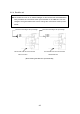
(a) The angle of the screen can be adjusted by loosening the lock screw on the deflection coil
assembly at the neck of the CRT tube and turning the entire screen. The user can also
adjust the screen position using the centering magnet.
4. Adjusting the C
4. Adjusting the C4. Adjusting the C
4. Adjusting the CRT display
RT displayRT display
RT display
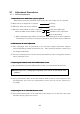
In addition to adjustment steps 1. to 3. explained above, CRT monitor adjustments in-
clude the following:
(a) Horizontal level adjustment CCN-366, L400
(b) Vertical size adjustment CCN-366, R353(V. S I ZE)
(c) Contrast adjustment CCN-366, R451(CONT)
(d) Focus adjustment CCN-366, R951
WARNING
Hi-voltage Caution
The CRT monitor (CCN-366) generates high electric voltage about 10kV and
on service personnel should touch parts inside the display.
Inadvertent manipulation may result in severe electric shock.
5. Adjusting the AVR output voltage
5. Adjusting the AVR output voltage5. Adjusting the AVR output voltage
5. Adjusting the AVR output voltage
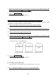
(a) Connect a high-precision voltmeter across pin TP1+3.3V on the CBD-1596 power supply
and the chassis, adjust potentiometer +3.3ADJ so that the output voltage reads +3.3
±
0.02V.
● Be sure to connect the scanner unit when making this adjustment.
Attention