Operation Manual Operation Manual Prior to use, please read this manual thoroughly. Keep this manual in a convenient place for quick and easy reference. XG14English.
XG14English.
Introduction ▋ ▋Greetings A Trim Input function can allocate trim levers to change numerical values of various functions (such as program mix values) during flight. A new function synchronizes the operation of servos on multiple flight control surfaces in real time. This completely eliminates the time lag where fast control inputs are required.
Introduction ▋ ▋General Safety Precautions * It is very important to ensure that you observe the following precautions. ▋About ▋ the Proportional System ▋Indications ▋ and Symbols Related to Safety This company cannot be responsible for any accident or failure that may occur from any modification of this product, use of non-genuine parts, natural disaster, or nonobservance of the precautions described in this manual.
Introduction ▋Rechargeable ▋ Battery and Battery Charger When adjusting the engine (motor), pay attention toDANGER dangers presented. DO NOT start the engine with the transmitter throttle in a high speed position. This is very dangerous. Abide by t he fol low i ng to prevent potent ia l leakage,explosion, heat generation, and fire. WARNING DANGER Failure can be caused. DO NOT use this module set in combination with a competitor’s product (servo, gyroscope, etc.). Malfunction can be caused.
Contents ▋ ▋Contents Elevator to Flap Mixing【ELEV → FLAP MIX】・ ・・・ Rudder to Aileron /Elevator Mixing・ 【RUDD → AILE/ELEV MIX】・・・・・・・・・・・・ Balance【BALANCE】 ・ ・・・・・・・・・・・・・ Flap Rate【FLAP RATE】・ ・・・・・・・・・・・・ Motor System【MOTOR SYSTEM】 ・・・・・・・・・ Camber sytem【CAMBER SYSTEM】・・・・・・・・ Brake system【BRAKE SYSTEM】 ・・・・・・・・・・ Flaperon Mixing【FLAPERON MIX】・ ・・・・・・・ Elevator to Camber Mixing・ 【ELEV → CAMB MIX】 ・ ・・・・・・・・・・・・・ Rudder to Spoiler Mixing・ 【RUDD → SPOI MIX】・ ・・・・・・・・・・・・・ Program Mixing【PROGRAM MIX 1-6】・・・
Preparation Lock ▋ ▋Switch Identification Stickers Unlock Lock Unlock Affix the sticker for your preferred model type. Remove any dust from the affixing surface, and then detach the sticker from the backing Lock paper. Next, apply the sticker to the transmitter surface, carefully matching the edges with the sticker area marked on the transmitter. ▋ ▋ ▋Stick Length Adjustment ▋Neck Strap Attachment Undo the recessed set screw located at the tip of the Unlock control stick.
Preparation ▋ ▋Inserting and Removing the transmitter battery 1) While pressing the embossed mark on the rear surface of the battery lid, Slide the lid in arrowed direction of the arrow. And remove. 2) Carefully insert the rechargeable battery connector into the transmitter battery connector. 3) Fit the rechargeable battery into the battery box together with filling sponge, and mount the battery cover, Battery boxnot to pinch the lead wires.
準備 ▋ ▋Notes on stick tension spring adjustment and the throttle stroke travel adjustment plate ▋This ▋ allows adjustment of the stick spring strength. ① Be certain to remove the battery before carrying out any adjustments. ② Remove the screws in the eight(8)locations on the rear case. Screws X 8 ③ Adjust the springs to the desired spring tension. By carefully adjusting each of the screws, you can achieve a range of spring tensions. ④ Close the rear cover, and tighten the screws.
Preparation ▋Throttle ▋ stroke travel adjustment By adding the Throttle stroke adjustment plate to the gimbal, the throttle stroke is limited by approximately 5 degrees. Be sure to install or remove the plate with reference to the drawing. When adding this "limiter plate" it is essential to recalibrate the throttle stick range. Be sure to follow this procedure. Note: Refer to the Page 76 "Transmitter Setting【TX SETTING】" in the system list for further details of calibration.
Preparation ▋ ▋Receiver Connections Receiver Connections to the servos and the power supply JR labels the channels on the receiver with names rather than numbers. From this point onward in the manual, the receiver channels will be described using their names. ※ Servos can be operated from a separate power supply by using the optional 'X-Bus power hub'. BATTRY RX HUB SENSOR Sensor Connections When connecting sensors, use a Y-Harness (sold separately) connected to the [BIND/BATT/SENS] terminal.
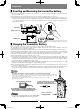
Preparation ▋ ▋Using the transmitter and receiver.▋ Receiver mounting location. ▋Please ▋ set up the antenna direction as per the following drawing. The 2.4GHz band radio waves are very directional. The receiver signal is very dependant on the direction of the antenna. Since the antenna receives radio waves from the sides rather than from the tip, please appropriately position the receiver antenna when installing the receiver in the model.
Weak Signal Strong Reception Strong Reception its radio waves, the receiving sensitivity will greatly differ depending on the direction against the antenna. Since the antenna receives radio waves from the sides rather than from the tip, please take adequate care of the antenna direction when installing the antenna in the model. Preparation The antenna part should be installed in a perfectly straight condition.
Preparation ▋ ▋Binding Procedure▋ (pairing the transmitter and receiver) In order for the transmitter and receiver to communicate, it is essential to pair or bind them together. Please follow this procedure: 1) Be sure that remote antenna unit is properly connected to the receiver. Locate the included bind plug, and ensure the transmitter and receiver batteries are fully charged. ※ Note that the Remote Antenna acts as both a receiver and also transmits data back to the transmitter.
CAUTION Functions Common to All Models ▋ ▋Names of Each Transmitter Control ▋Helicopter ▋ Type The names in square brackets 【】 are the abbreviated characters displayed on each setting screen. Helicopter JR gives each switch or lever a name rather than a number on the transmitter. The names and positions are different depending on the model type. Please note this when reading the manual. Mode 1 Example Pilot Lamp(LED) Hovering pitching trim 【HV.P/LTRM】 Airplane Display: During transmission: Blue.
CAUTION Functions Common to All Models Helicopter ▋ ▋Names of Each Transmitter Control ▋Airplane ▋ Type The names in square brackets 【】 are the abbreviated characters displayed on each setting screen. Pilot Lamp(LED) Display: During transmission: Blue. Pilot Lamp(LED) Mode 1 Example Mode 1 Example AUX Trim【AUX/LTRM】 AUX Trim【AUX/LTRM】 Flap Switch【FLAP SW】 Flap Switch【FLAP SW】 Mixing Switch【MIX SW】 Mixing SW】 RudderSwitch【MIX Dual rate Switch Airplane During low output transmission: Blue, flashing.
Functions Common to All Models ▋ ▋Names and Functions of the Input Keys In addition to the standard button keys for input, this transmitter employs a jog-dial. When programming the transmitter, almost all operations can be performed very intuitively using this dial. The dial is used by rotating it left or right, and pressing it. A “click” sound is heard confirming a valid input. A “click” sound may also be heard without any change to the numerical numbers on the display.
Integrated Timer Functions to All Models Model Common No. Transmitter Power Source Voltage Receiver Power Source Voltage Model Name where In the where ▋ situationoperating, ▋Initial INFO Screen Servo Hold is operating, this will be displayed. displayed. Timer 1 Timer 2 Integrated Timer Flight Mode Transmitter Power Source Voltage Trim Position Display Receiver Power Source Voltage Model No. Model Name In the situation where where Servo Hold is operating, operating, this will be displayed. displayed.
Functions Common to All Models ▋ List Screen ▋My ▋My ▋ List Function My List initial Condition Frequently used functions can be selected and displayed on the customizable ‘My List’ for quick access. Pressing the ENTER key while on the normal screen will select the My List display. Nothing will be displayed on the My List screen until it has been customized. To add f u nc t ion s to t h i s l i st , pr e s s t he lowermost Function key. The display will be shown and “EDIT MODE” will flash.
Functions Common to All Models ▋ ▋Navigation during Model Setting When a new model has been created, or when the model type has been changed, it is necessary to enter basic initial information. 1) Type selection 2) Model Name 3) Complete some basic setup information depending on the model type selected, as shown below.
CAUTION Functions Common to All Models ▋ ▋FLIGHT MODE ▋Function ▋ Explanation Helicopter The Flight Mode function allows switching between various aircraft settings using a switch. This means it is possible to select aircraft flight characteristics using a ‘one-touch’ operation. The maximum number of flight modes which can be selected varies with model type.
Functions Common to All Models ▋Glider ▋ flight mode ▲▲ SPEED ▲▲ CRUISE ▲▲ THERMAL △△ LAND △△ LAUNCH ▽▽ DIST ▽▽ ZOOM ▽▽ FREE ※ Glider flight modes are not activated by default. It is possible to activate these flight modes in the system list, "DEVICE SELECT". ※ By setting the “SPEED” it is possible to utilize ▲ marked mode which are CRUISE and THERMAL. ※ If require to have further flight mode, select “LAUNCH”. Depending on selecting the type of the toggle switch, certain flight mode is selectable.
CAUTION Function List ▋ ▋DUAL-RATE & EXPONENTIAL【D/R&EXP】 ▋Function ▋ Explanation Helicopter This function switches aileron, elevator, and rudder control surfaces between different control surface angles and curves, using the Dual Rate switches. By combining the control surface angles with exponential settings, it is possible to carry out various independent settings so that the aircraft response can be changed.
CAUTION Function List ▋ ▋Travel adjust【TRAVEL ADJUST】 ▋Function ▋ Explanation Helicopter This function allows independent adjustment of the servo left/right (or up/down) movement, for each channel. The adjustment is carried out with reference to the neutral position. Adjustment is possible over an adjusting range between 0 and 150% in each direction. The default value is 100%, and this gives standard servo movement.
Helicopter Function List Airplane ▋ ▋Limit Adjust【LIMIT ADJUST】 ▋Function ▋ Explanation Glider When multiple channel mixing is used, the resultant servo movement angle may become too large, and an unreasonable force be applied to the linkages. If limit values are set, it is possible to limit the maximum movement of the servos, regardless of programmable mixing, etc. ▋Setting ▋ Method Set the limit values separately for left/right and up/down directions for each channel (servo).
CAUTION Function List ▋ ▋Sub Trim【SUB TRIM】 ▋Function ▋ Explanation Helicopter This allows fine trimming of the servos attached to each channel. This trim should be used as a fine adjustment when the servo horn mounting angle is not 90 degrees with regard to the linkage. Note that if large amounts of sub trim is used, it will affect the maximum deflection of the servo. It is therefore recommended to use only small values here.
CAUTION Function List ▋ ▋Reverse Switch【REVERSE SW】 ▋Function ▋ Explanation Helicopter This function reverses the servo operating direction (pulse change direction) of each channel. ▋Setting ▋ Method Rotate the dial to move to and select the channel that you wish to change (inverse display). Then press the dial to select the rotation direction. “NORM” is the normal direction and “REV” is the reverse direction. Actually operate the servos and carefully confirm the settings before flying.
調整ポイント表示 Function List 現在の フライトモード位置 各調整ポイントの 入力位置と出力位置 ▋ ポイントの ▋Servo Speed【SERVO SPEED 】 カーブをコピー 注意: グラフはホバリン グスロットルやス ロットルトリムで 変化する場合もあ ります。 CAUTION 追加と削除 ▋Function ▋ Explanationポイント接続を曲線に変更 Helicopter スティック入力位置と出力位置の数値表示 This function slows down the operation speed of the servos independently for each channel. This function should be considered as a speed limiter. The speed setting can be set separately for left/right (up/down).
CAUTION Function List ▋ ▋Throttle Curve【THRO CURVE】 ▋Function ▋ Explanation Helicopter This function adjusts throttle servo operation in response to throttle stick operation. The servo position can be set independently for a maximum of 7 point positions. In addition, an EXPO (exponential) function is also incorporated to allow smooth throttle stick connection of each of the points. This function is available in each Flight Mode for helicopters (maximum 5), and 2 modes for airplanes.
ポイントの 追加と削除 ポイント接続を曲線に変更 スティック入力位置と出力位置の数値表示 Function List ダイヤル ▋For ▋ Airplane There is one kind of throttle curve available and it is possible to change the curve at any time with a toggle switch , flight mode switch or the throttle stick. TIPS The numerical value “IN” shows the position of the throttle stick and the numerical value “OUT” shows the output value to the servo. Adjustment is possible over an adjusting range between 0 and 100% for each of the Slow or High (up or down) directions.
CAUTION Function List ▋ ▋Pitch Curve【PITCH CURVE】 ▋Function ▋ Explanation Helicopter This function adjusts pitch operation in response to throttle stick operation. The servo position can be set independently for a maximum of 7 point positions. In addition, an EXPO (exponential) function is also incorporated to allow smooth throttle stick connection of each of the points. This function is available in each Flight Mode for helicopters (maximum 6), and 2 modes for Airplane Caution: airplanes.
CAUTION Function List ▋ ▋Tail Curve【TAIL CURVE】 ▋Function ▋ Explanation Helicopter This is the mixing between the pitch and the tail servo. It is also known as revolution mixing. It allows setting of the mixing amounts separately up and down from the hovering point. Intermediate points can also be established in each direction, so that setting can be freely carried out. In addition, Mixing Rate setting, which is convenient for detailed adjustment of stunt positions, will also be possible.
CAUTION Function List ▋ ▋Throttle hold【THRO HOLD】 ▋Function ▋ Explanation Helicopter This function is for autorotation landings – it holds the Throttle Servo at a low position. Using a selected switch, the engine can be cut, or fixed at an optional slow position. Further, there is also a Stick Auto function that allows switching of the servo to the Hold position when the stick is lowered to a preset position. ▋Setting ▋ Method Airplane This function is “INH” by default. Set the function to ACT.
CAUTION Function List ▋ ▋Gyro Sensitivity【GYRO SENS】 ▋Function ▋ Explanation Helicopter This function controls the gyro sensitivity using the GEAR channel, and the Auxiliary (AUX) channel if required. It allows adjusting the gyro sensitivity from the transmitter. Further, it supports “Dual Gain” as employed in JR’s G7000 where two channels are required. Additionally, the use of two gyro units is also possible.
Display Displayfor forcorresponding corresponding flight flightmode mode Function List Gyro GyroMode Modeselection selection TRIPLE TRIPLEAXIS AXISMODE MODE Calibration Calibrationfunction function TIPS Follow and understand the details of the TAGS01 3 axis gyro manual completely prior to using this calibration function. The upper numerical values are the The upper numerical values are the Setting Settingvalues valuesand andactual actualoutput outputvalues values setting settingvalues. values.
CAUTION Function List 調整ポイント表示 ▋ ▋Governor 【GOVERNOR】 カーブをコピー 注意: グラフはホバリン Helicopter グスロットルやス A governor maintains the rotor rotation speed at a uniform value. This function sets the ロットルトリムで rotation speed of the Governor to各調整ポイントの aid in stable flight. Different rpm settings can be made separately for each 変化する場合もあ Flight Mode.
CAUTION Function List ▋ ▋Swash Mixing【SWASH MIX】 ▋Function ▋ Explanation Helicopter This function sets the mixing relating to the swash plate and swash plate servos (1-4) to allow coordinated control of the helicopter. This swash mixing is essential for helicopters that incorporate CCPM systems. CCPM is a type of pitch mixing in which the servos are directly linked to the swash plate. In this transmitter, 7 types of swash plates can be selected.
CAUTION Function List ▋ ▋Throttle trim【THRO TRIM】 ▋Function ▋ Explanation Helicopter This function sets the Throttle Trim movement, and additionally a Throttle Cut function is provided for cutting the engine. There is a Trim Memory function for cutting the engine using the Trim. Note that for airplanes, an Idle Adjust function is also incorporated that allows separate detailed setting of the idle position.
Function List 調整ポイント表示 現在の フライトモード位置 入力位置と出力位置 ▋ ▋Throttle Mixing【MIX → THRO】 ポイントの 各調整ポイントの ▋Function ▋ Explanation 追加と削除 カーブをコピー 注意: グラフはホバリン グスロットルやス ロットルトリムで 変化する場合もあ ります。 CAUTION Helicopter ポイント接続を曲線に変更 スティック入力位置と出力位置の数値表示 When operating various controls on a helicopter, the rotor rotation may be reduced due to loading. This function is a mixing function for implementing a correction for this effect. It will allow corrections of the rotor rotation speed normally carried out by a governor.
調整ポイント表示 Function List カーブをコピー 注意: グラフはホバリン グスロットルやス ロットルトリムで 変化する場合もあ ります。 現在の フライトモード位置 各調整ポイントの 入力位置と出力位置 CAUTION ポイントの ▋ ▋Flight Mode Delay【FLIGHT MODE DELAY】 追加と削除 ポイント接続を曲線に変更 ▋Function ▋ Explanation スティック入力位置と出力位置の数値表示 Helicopter When the Flight Mode is changed, the servos may move suddenly, causing a jerky reaction in flight. To prevent this, it is possible to set a time to each channel separately, during which the servo will move slowly to the new position when switching Flight Modes.
CAUTION Function List Helicopter ▋ ▋FLAP SYSTEM【FLAP SYSTEM】 ▋Function ▋ Explanation Airplane The flaps can be controlled in three stages using a switch. A flap delay is also possible. Additionally, there is a function that carries out mixing to the elevators. There is also an Auto Throttle function that automatically lowers the flaps when the throttle stick is lowered.
CAUTION Function List Helicopter ▋ ▋SNAP ROLL【SNAP ROLL】 ▋Function ▋ Explanation Airplane This function is useful for executing Snap Rolls. There are four types of presets, and normally activation is carried out using the Snap switch. However, Stick switches are also incorporated that automatically enter a Snap Roll when the stick is operated by a fixed amount. Further, it is also possible to select which Flight Modes the Snap switches are active in.
CAUTION Function List Helicopter ▋ ▋Differential 【DIFFERENTIAL】 ▋Function ▋ Explanation Airplane This function can be used when the aileron, rudder, and flap channels have been set to Dual Channel (two servos are set to each control surface). Taking ailerons as an example, if the wing is a high-lift style, when the ailerons are moved up and down by the same angle, greater air resistance will be generated on the underside, causing the aircraft to yaw in the opposite Glider direction to the intended turn.
Trim Input Function (TRIM IN) Function List ▋For ▋ Glider It is possible to set each control surface (Aileron, Rudder, Flap & Brake) to the flight mode switch. Channel Display Differential Amount Flight Mode Aileron Differential (AILE) Settings can be activated for the below Wing types. Flaperon (FLAPERON) 4 Aileron (4-AILE) ※ On 4-Aileron usage, each control can be paired with following setting separately.
CAUTION Function List Helicopter ▋ ▋Aileron to Rudder Mixing【AILE → RUDD MIX】 ▋Function ▋ Explanation Airplane This function allows smooth coordinated turns for scale model aircraft. In addition, in glider models, the Break function automatically releases this mixing when rudder or elevator operation is sensed. ▋Setting ▋ Method Glider ▋For ▋ Airplane Aileron to Rudder mixing can be set independently on Right and Left. It is possible to activate with any desired switch.
CAUTION Function List Helicopter ▋ ▋Aileron to Flap Mixing【AILE → FLAP MIX】 ▋Function ▋ Explanation Airplane This function mixes the aileron operation to the Flaps. This allows maneuvering using only Aileron to minimize the generation of air resistance when you wish to speed up the roll rate. ▋Setting ▋ Method Glider In order to activate this function, it is necessary to set “DUAL FLAP” under ”WING TYPE” on the System List.
CAUTION Function List Helicopter ▋ ▋Elevator to Flap Mixing【ELEV → FLAP MIX】 ▋Function ▋ Explanation Airplane This function mixes elevator operation to flaps, for so-called ‘air combat flaps’ (snap flaps). ▋Setting ▋ Method The mixing amount from Elevator to Flaps can be set separately for both up and down movement. It is possible Glider to allocate the switch to a desired position, or use the flight mode switch to control this mix. Operation Condition This sets the mixing amount to the flaps.
CAUTION Function List Helicopter ▋ ▋Rudder to Aileron /Elevator Mixing▋ 【RUDD → AILE/ELEV MIX】 ▋Function ▋ Explanation Airplane This function mixes Rudder operation to the Ailerons and Elevators. This is convenient for removing biases in knife-edge flight. In addition, a Trim Input Switch convenient for making adjustments during flight can be Glider used. ▋Setting ▋ Method The mixing amounts from Rudder to Aileron and Elevator can be set separately for left and right as two independent settings.
CAUTION Function List Helicopter ▋ ▋Balance 【BALANCE】 ▋Function ▋ Explanation Airplane The “BALANCE” functions is used to correct for individual servo characteristic to equalize the travel of each control. This is useful when using Six Ailerons, Four Ailerons, Dual Elevators, and Dual Flaps. It is useful when more than two servos are used per control surface. ▋Setting ▋ Method Glider The initial Balance setting points are three points set to the slow, center and high sides.
Function List 調整ポイント表示 カーブをコピー 注意: グラフはホバリン グスロットルやス ▋For ▋ Glider ロットルトリムで Setting can be achieved for the 各調整ポイントの below Wing types. Set the Wing type in the system list. 変化する場合もあ ります。 入力位置と出力位置 Flaperon (FLAPERON) 現在の フライトモード位置 It is possible to correct the right Aileron’s servo movement based on the left Aileron’s servo movement. ポイントの ※ This transmitter is set as Flaperon as追加と削除 the default wing setting for Glider.
Helicopter Function List Airplane ▋ ▋Flap Rate【FLAP RATE】 現在の 調整ポイント表示 カーブをコピー 注意: グラフはホバリン グスロットルやス Glider フライトモード位置 ロットルトリムで This function sets the maximum up and down movement of the flap control surface変化する場合もあ angles 各調整ポイントの ります。 入力位置と出力位置 independently in each Flight Mode when using the Flap Lever. ▋Function ▋ Explanation It is also possible to set the flap amount against Aileron movement.
Helicopter Function List Airplane ▋ ▋Motor System【MOTOR SYSTEM】 ▋Function ▋ Explanation Glider This function is used to switch off (HOLD) the motor channel by using the Gear switch (default) or by selecting various flight mode positions. By using the Delay function, it is possible to smoothly run the motor from low r.p.m. to higher r.p.m. in a linear transition (Note: The speed controller must have a linear transition to activate this function).
Helicopter Function List Airplane ▋ ▋Camber sytem【CAMBER SYSTEM】 ▋Function ▋ Explanation Glider It is possible to set an airplane (Glider in particular) which has full span ailerons or flaps + ailerons on the main wing giving full-span moveable control surfaces. These control surfaces can be moved up and down simultaneously to change the wing type. Because changing the wing type can vary the rate of descent and the drag, it is possible to change the flight endurance and the glide ratio.
Helicopter Function List Airplane ▋ ▋Brake system【BRAKE SYSTEM】 ▋Function ▋ Explanation Glider This function creates air brakes using the spoilers, ailerons, and flaps. The function is also known as Butterfly mixing and Crow mixing. When the spoiler stick is lowered, the flaps will lower and the ailerons will be lifted. Looking from the front of the aircraft you will see the whole wing will no longer generate lift, and will have a huge amount of drag.
Helicopter Function List Airplane ▋ ▋Flaperon Mixing【FLAPERON MIX】 調整ポイント表示 カーブをコピー ▋Function ▋ Explanation 注意: Glider グラフはホバリン グスロットルやス ロットルトリムで "Aileron -> Flap Mixing" �������� This mixes from Aileron to f lap, to use the f laps as Ailerons 変化する場合もあ 各調整ポイントの therefore the roll rate can be increased. ります。 as Flaps. 入力位置と出力位置 "Flap -> Flaperon Mixing" ������� This mixes from Flap to Aileron, to use the Ailerons 現在の This function allows the setting of Flaperon mixing.
Helicopter 調整ポイント表示 Function List カーブをコピー 注意: グラフはホバリン グスロットルやス ロットルトリムでAirplane 変化する場合もあ ります。 現在の フライトモード位置 各調整ポイントの 入力位置と出力位置 ▋ ▋Elevator to Camber Mixing▋ ポイントの 追加と削除 【ELEV → CAMB MIX】 ポイント接続を曲線に変更 スティック入力位置と出力位置の数値表示 Glider ▋Function ▋ Explanation This function applies mixing to the main wing camber (Center line of Airfoil) based on elevator operation. Adjustment of the wing root flaps and wing tip flaperons separately in both up and down direction is possible.
注意: グラフはホバリン グスロットルやスHelicopter ロットルトリムで 変化する場合もあ ります。 現在の フライトモード位置 Function List 各調整ポイントの 入力位置と出力位置 ポイントの 追加と削除 Airplane ▋ ▋Rudder to Spoiler Mixing▋ 【RUDD → SPOI MIX】 ポイント接続を曲線に変更 スティック入力位置と出力位置の数値表示 ▋Function ▋ Explanation Glider ダイヤル This function emulates rudder operation using spoilers when the aircraft is equipped with dual spoilers. This yaw method is also known as drag rudder. According to the rudder operation, the left and right spoilers alternately operate.
CAUTION Function List ▋ ▋Program Mixing【PROGRAM MIX 1-6】 ▋Function ▋ Explanation Helicopter If a mixing function is required that is not already incorporated in the transmitter, six program mixing systems are provided for use. These can be used to freely structure your own mixes. For this mixing, either simple normal mixing or curve mixing that allows setting of a curve using multiple points can be selected.
Function List Curve Mixing Mixing Offset on reference pointfunction, move the Mixing for value By default, this is set to “INH”. Select CURVE using this Program Mixing. To “INH” this cursor to the Master/Slave channel selection, then press the CLR key.
Function List ▋Name ▋ of the Master Channel and its purposes.▋ Hold Delay (HOLD DELAY) Explanation of the “INCLUDE” function. ▋INCLUDE ▋ If there are several sets of Mixing set on the program mixing, there is no connection between those Mixing each other. If the “INCLUDE” setting is used provided, it is capable to include relevant mixing to be set in one Mixing to avoid complexity , It simplifies the mixing set up.
Function List ▋For ▋ Glider Channel name Ch1: Flaperon (FPRN) Ch2: Aileron (AILE) Ch3: Elevator (ELEV) Ch4: Rudder (RUDD) Ch5: Gear (GEAR) Ch6: Flap (FLAP) Ch7: Ch8: Ch9: Ch10: Ch11: Ch12: Ch13: Ch14: Extra: AUX2 AUX3 AUX4 AUX5 AUX6 AUX7 AUX8 AUX9 #SPO FMOD TRNR MOTO Items which can be Included Flaperon Mixing (FPRN MIX), Camber System(CAMB SYS), Brake system (BRAKE SYS), Elevator=>Flap MIX(ELEV->FLAP), Flap Rate (FLAP RATE) Aileron Trim, Dual Rate (D/R&EXP), Camber system (CAMB SYS) Trim, Dual Rate (D/R&
Function List ▋For ▋ Airplane Channel name Ch1: Ch2: Ch3: Ch4: Ch5: Ch6: Ch7: Ch8: Ch9: Ch10: Ch11: Ch12: Ch13: Ch14: Throttle (THRO) Aileron (AILE) Elevator (ELEV) Rudder (RUDD) Gear (GEAR) Flap (FLAP) AUX2 AUX3 AUX4 AUX5 AUX6 AUX7 AUX8 AUX9 ETC: FPRN AILV RDVT FLAI ▋For ▋ Glider Items which can be Included If the Wing type is selected as “DUAL ELEV” or “4-AILE”or “6-AILE” it is possible to arrange mixing on Aileron as a flap.
CAUTION Function List ▋ ▋TIMER 【TIMER】 ▋Function ▋ Explanation Helicopter This transmitter incorporates two Independent Timer systems as well as an Integrated Timer. Each system has two types of timer . a count down timer and a stop watch timer. The timer can be operated in Flight Modes and through free switch selection. ▋Setting ▋ Method Airplane DOWN TIMER Initially, the timer function is inhibited - “INH”. Select (INH) and press the dial and select the “Down Timer”.
CAUTION Function List ▋ ▋MIXING MONITOR【MIX MONITOR】 ▋Function ▋ Explanation Helicopter This screen gives a listing and confirmation of each of the mixing conditions and basic settings incorporated in the transmitter. Because all the mixing that has been incorporated in each model will be displayed regardless of whether it is set to INH or ACT, it will also be possible to discover unintentional setting mistakes.
CAUTION Function List ▋ ▋SERVO MONITOR【MONITOR】 ▋Function ▋ Explanation Helicopter This function allows simulation of servo operation on the transmitter. Because this gives a ‘final output’ of all servo signals, provisional confirmation can be carried out before actually connecting the servos. Further, this is useful for discovering unintentional mixing and switch setting mistakes. ▋Setting ▋ Method Airplane Servo test outputs are displayed on the screen.
CAUTION System List ▋ ▋MODEL SELECT【MODEL SELECT】 ▋Function ▋ Explanation Helicopter Here it is possible to start setting up a new model and switch between existing models. Up to 30 unique models can be stored in this transmitter. ▋Setting ▋ Method For safety reasons, a screen initially appears confirming that you wish to stop radio wave transmission. Select “YES” to continue to this function screen. Next, the current Model No. and Model Name will be displayed. Select this item and press the dial.
CAUTION System List ▋ ▋MODEL COPY & ERASE【MODEL COPY/ERASE】 ▋Function ▋ Explanation Helicopter In this screen, copying and erasing of model data is carried out. This can be carried out on both the transmitter memory and on an SD Card. In addition, it is possible to copy model data between other matching JR transmitters that have been connected using a trainer cable. ▋Setting ▋ Method Airplane For safety reasons, a screen initially appears confirming that you wish to stop radio wave transmission.
ります。 入力位置と出力位置 ポイントの 追加と削除 System List ポイント接続を曲線に変更 スティック入力位置と出力位置の数値表示 ダイヤル Model Erase Model in use Model data stored on the “INTERNAL” memory or SD CARD can be erased. Be sure to double check the model being erased before continuing. ※ If the currently selected model is erased, the new model creation wizard will automatically start. If wish to use the current model number, be sure to copy it to another model number first and erase the particular model by Model Select.
CAUTION System List 調整ポイント表示 カーブをコピー ▋ ▋Model Type Select【TYPE SELECT】 ▋Function ▋ Explanation 現在の フライトモード位置 This function allows selection of model type. 各調整ポイントの The type can be switched between Helicopter ⇔ Airplane ⇔ Glider. 入力位置と出力位置 Additionally, this screen will be automatically displayed when creating a new model.
CAUTION System List ▋ ▋Model Name【MODEL NAME】 ▋Function ▋ Explanation Helicopter In this screen, the inputting and modification of each model name can be carried out. Select the name from the list of characters and numbers. The Name can contain a maximum of 8 characters. 調整ポイント表示 カーブをコピー Display showing the Heli type as an Example. 現在の フライトモード位置 各調整ポイントの 入力位置と出力位置 Display showing the Heli type as an Example.
CAUTION System List ▋ ▋Flight Mode Name【FLIGHT MODE NAME】 ▋Function ▋ Explanation Helicopter In this screen, the name given to the Flight Modes can be changed. The Flight Mode name display is shown with two names, one long name up to six (6) characters and one short name up to four (4) characters, which are used in each of the screens, and each can be freely changed. 調整ポイント表示 カーブをコピー Airplane 注意: グラフはホバリン グスロットルやス ロットルトリムで 変化する場合もあ Glider ります。 Display showing the Heli type as an Example.
CAUTION System List ▋ ▋Trim System【TRIM SYSTEM】 ▋Function ▋ Explanation Helicopter In this screen, the various settings relating to the Trims can be changed. The resolution of each Trim, the Trim type, whether separate or common trims should be used for each flight mode can be set. Using this function, customers can easily change the trim settings. ▋Setting ▋ Method Airplane Trim Step It is possible to set the trim travel amount per one (1) click. The default is Four (4) steps per click.
Trim step Flight Mode Trim Setting COM : Common FMOD : Individual trims for each Flight Mode System List FMOD : Individual trims for each flight Mode. Flap Trim ON/OFF (FLAP TRIM) It is possible to select the flap trim as active or inactive. Cross Trim setting Type of Trims Two :trims can be switched around (Cross Trim) in order to set the trim to the opposite side of the transmitter NORM Standard Trim 調整ポイント表示 カーブをコピー so as: trim be adjusted without removing from the control stick.
CAUTION System List ▋▋Stick Position Switch【STICK POSITION SW】 ▋Function ▋ Explanation Helicopter This is a convenient function that allows switching (ON/OFF) of virtual switches using stick operation. Virtual switches can be programmed to any stick position, and then used to switch various functions On and Off. This function can be used as a virtual switch for Programmable Mixers, turning the mix on or off. Additionally, a stick position switch can be used start or stop a timer.
System List 調整ポイント表示 カーブをコピー 現在の フライトモード位置 ▋ 入力位置と出力位置 ▋Trim input Switch 【TRIM INPUT SWITCH】 各調整ポイントの ▋Function ▋ Explanation CAUTION 注意: グラフはホバリン グスロットルやス ロットルトリムで 変化する場合もあ ります。 ポイントの 追加と削除 Helicopter This function allows adjustment of Mixing values or the Sensitivity value for Gyro settings, ポイント接続を曲線に変更 スティック入力位置と出力位置の数値表示 using a chosen trim lever. It is a very useful function which enables fine tuning during flight. ▋Setting ▋ Method There are four types of Trim Input switch.
CAUTION System List ▋ ▋Stick Alert【STICK ALERT】 ▋Function ▋ Explanation Helicopter This function will sound an alert when the Throttle Stick reaches a certain position. It is convenient to confirm the hover position or zero pitch with an alert. ▋Setting ▋ Method The initial setting is “INH”. First set this to “ACT”. Adjust the stick position to where the alert should activate. If necessary, use “SW SEL” to couple with a flight mode or other switches to use this function.
CAUTION System List ▋ ▋Warning 【WARNING】 ▋Function ▋ Explanation Helicopter If the Throttle Stick or Flight Mode switches are set to potentially dangerous positions when the transmitter is switched on, an alert is triggered. A warning will be displayed on the LCD screen, and radio waves will not be emitted until the throttle stick and flight mode switches have been returned to safe positions. ▋Setting ▋ Method First change “INH” to “ACT”, to activate this function.
CAUTION System List ▋ ▋Transmitter Setting【TX SETTING】 ▋Function ▋ Explanation Helicopter This function allows basic adjustment of transmitter settings such as LCD display mode, sound (audio) mode, etc. ▋Setting ▋ Method Airplane LCD Backlight Lighting Condition LCD Contrast Audio mode This allows selection of the sound tone in each operation.
CAUTION System List ▋ ▋Trainer 【TRAINER】aka: Buddy Box in the USA ▋Function ▋ Explanation Helicopter This function allows two (2) transmitters to be connected via a Trainer cable (available separately) to allow dual control flight instruction. A skilled pilot can teach a beginner how to fly an aircraft using this trainer system. The XG14 can function as Master (Trainer) or Slave (Trainee).
System List 調整ポイント表示 現在の フライトモード位置 CAUTION カーブをコピー ▋ ▋Bind and Range各調整ポイントの Check【BIND&RANGE】 入力位置と出力位置 ▋Function ▋ Explanation 注意: グラフはホバリン グスロットルやス ロットルトリムで 変化する場合もあ ります。 ポイントの This function allows binding (pairing) with the receiver. In addition, transmitter power output 追加と削除 can be reduced for carrying out a range check. ▋Setting ▋ Method ポイント接続を曲線に変更 Helicopter スティック入力位置と出力位置の数値表示 Airplane ダイヤル Bind Mode Glider Binding (BIND) Set the receiver to the Bind Standby condition.
CAUTION System List ▋ ▋Telemetry System【TELEMETRY】 ▋Function ▋ Explanation Helicopter This allows confirmation of the telemetry sensors present in a particular aircraft, gathering information such as Receiver Voltage, Altitude, Temperature or Propeller or rotor blade r.p.m., etc. In addition to the data on the display, alarms are used, so as aircraft conditions can be monitored without taking your eyes off the aircraft.
System List Initial Delay (INITIAL DELAY) In order to detect the Signal Pulse from the Brushless motor, it is essential to use ESC, however, certain ESC on the R/C market offers the function to alert initial start with sound of beep. This canbe recognised as a highest RPM signal on this sensor, So False RPM may appear on the data screen.
System List TIPS By using the Information screen, it is possible to display your desired Telemetry information on the first page, together with the Timer and Flight Mode selection on a screen that customers can customize so that it is easy to check. Initially it is set as Inhibited. Select the telemetry information to be displayed, and allocate it to a position on the screen. ▋Caution ▋ Note Rotate the dial to the right to access the first page.
CAUTION System List ▋ Servos Hold【ALL SERVOS HOLD】 ▋All ▋Function ▋ Explanation Helicopter ▋Setting ▋ Method Airplane This function holds (locks) all the servos in their current positions. It is used when the operator does not wish the servos to move, typically during some radio adjustments. When this function is set to on, a “SERVO HOLD” message will flash on the left side of the Initial INFO screen.
CAUTION System List ▋ ▋Device Select【DEVICE SELECT】 ▋Function ▋ Explanation Helicopter This screen is where various flight modes can be set, and where switch functions can be defined. Further, channel output assignments can be made here.
Selection of Extension Switch Flight mode Extension Switch System List Selection of Extension Switch Device Select Selection of output Device Select Selection of output ▋For ▋ Airplane Flight mode Extension Switch Selection of Extension Switch Flight mode Extension Switch Device Select Flight mode Extension Switch Device Select Selection of output Selection of output Flight Mode Switch (FLIGHT MODE) Initially, it is set to “INH”. Select the switch to control flight mode selection here.
System List Speed / Launch Switch (SPEED/LAUNCH) 調整ポイント表示 カーブをコピー By setting up both a SPEED(Speed Switch)and LAUNCH(Launch Switch)it is possible to set flight Modes. ① SPEED (Speed Switch) By setting a Speed switch, it is possible to use this flight mode.
CAUTION System List ▋ ▋Swash type【SWASH TYPE】 ▋Function ▋ Explanation Helicopter ▋Setting ▋ Method Airplane This function allows electronic CCPM mixing to match the mechanical structure and control of the helicopter swash plate. After making the SWASH TYPE selection, detailed settings should be made using Swash Mixing in the Function List. Glider Swash Types Select the CCPM Swash type on the screen by rotating the dial, and then pressing the dial.
CAUTION System List Helicopter ▋ ▋Wing Type【WING TYPE】 ▋Function ▋ Explanation Airplane Here the wing type can be set. Dual ailerons and dual flaps, dual elevators, dual rudders, tailless planes, and V-tail wings can be selected. ▋Setting ▋ Method Glider ▋For ▋ Airplane Wing Type Tail Type Dual Channel/Mate Trim Dual Trim Setting Wing Type (WING) Select the Main Wing Type. ፧፧Normal (NORMAL) For standard airplane wing types. ፧፧Flaperon (FLAPERON) For wings with Dual Aileron.
System List Tail (TAIL) ፧፧Normal(NORMAL) Standard tail wing setting ፧፧V-Tail (V-TAIL) To perform mixing for a V-Tail airplane. The following channel outputs are used: Wing Type Channel 3 (ELEV) : Left Tail (LTAL) Channel 4 (RUDD) : Right Tail (RTAL) ፧፧4 Elevator (4ELEV) For models with 4 Elevators The Following channel outputs are used.
CAUTION System List ▋ ▋Fail safe【FAIL SAFE】 ▋Function ▋ Explanation Helicopter ▋Setting ▋ Method Airplane If the receiver does not receive a valid RF signal from the transmitter, this function moves the servos to predefined positions, to avoid the scenario of the aircraft crashing at, for example, full throttle. Be sure to set the Fail Safe before flying each aircraft. This function allows selections to be made for each channel in case of loss of RF signal.
CAUTION System List ▋ ▋Throttle Stick Direction▋ 【THRO (SPOI) STICK DIRECTION】 ▋Function ▋ Explanation This enables the Throttle Stick (Spoiler Stick) direction to be reversed without changing the output signal value – the input value gets changed. This is a completely different function from using the Reverse switch function. ▋Setting ▋ Method 調整ポイント表示 Helicopter Airplane カーブをコピー 注意: グラフはホバリン グスロットルやス Glider ロットルトリムで 変化する場合もあ ります。 現在の フライトモード位置 各調整ポイントの 入力位置と出力位置 ポイントの 追加と削除 ポイント接続を曲線に変更 REV.
CAUTION System List ▋ ▋Stick Mode【STICK MODE】 ▋Function ▋ Explanation Helicopter This function changes the stick mode between Mode 1, Mode 2, Mode 3 & Mode 4. In the USA, Mode-2 is commonly used. In Japan, Mode 1 is the most common configuration. ▋Setting ▋ Method The initial setting is determined by the mode the radio was in when purchased. This function can be used to change this mode.
CAUTION System List ▋ ▋XBus Function【X.BUS】 ▋Function ▋ Explanation Helicopter This XG14 has all new X-Bus system using JR's own serial bus data instead of PWM (Pulse Wide Modulation) to communicate with X-Bus products such as servos. Control signals are sent in a serial manner to all channels, with individual servos recognizing their own data from receiver. ※ It is required to use X-Bus capable receiver system in order to perform Serial data transmission.
System List Main ID on Left and Sub ID on Right for compliant Device. Main ID on Left and Sub ID on Right for compliant Device which need to change ID. Set the Cursor on the specific item and Press the scroll dial to finalize. This is the value of the SETTING amount that determines how precisely the servo moves for one increment of increase-decrease. (similar to trim step) It can be set between 1% - 10% with 1% offering fine control and 10% coarse adjustment.
CAUTION Data Sheet ▋ ▋XG14 DATA SHEET / HELI ▋MODEL ▋ No. ▋MODEL ▋ NAME FLIGHT MODE NAME Helicopter NORMAL(NORM) STNT-1(ST-1) STNT-2(ST-2) STNT-3(ST-3) STNT-4(ST-4) HOLD(HOLD) Airplane LONG SHORT THRO AILE ELEV RUDD GEAR PIT.
CAUTION Data Sheet ▋ ▋XG14 DATA SHEET / HELI AILE POS 0 D/R EXP NORM FM-AUTO ELEV NORM FM-AUTO RUDD NORM FM-AUTO % % % % % % % % % % % % % % ST-2 ST-3 POS 1 ST-4 HOLD POS 2 % POS 3 POS 4 % % % % % % % % % % % % % % % % % % ST-2 ST-3 POS 1 ST-4 HOLD POS 2 % POS 3 POS 4 % % % % % % % % % % % % % % % % % % ST-3 ST-4 HOLD % INPUT 1s・2s180° ・3s120° ・3s140°/135° ・3s90° ・4s90° ・4s45° AILE % PIT.
CAUTION Data Sheet ▋ ▋XG14 DATA SHEET / HELI ACT・INH STICK ALERT POS ON・NORM・ST-1・ST-2・ST-3・ST-4・HOLD・AILE-0/1/2・ ELEV-0/1/2・RUDD-0/1/2・GEAR-0/1/2・AUX2-0/1/2・ FMOD-0/1/2・HOLD-0/1・TRN-0/1/2・SPS-0/1 TRIM THRO STICK DIRECTION Helicopter REV・NORM STICK MODE Airplane SW SELECT TIS 0 AND・NORM・ST-1・ST-2・ST-3・ST-4・HOLD・AILE-0/1/2・ELEV-0/1/2・RUDD-0/1/2・GEAR0/1/2・AUX2-0/1/2・FMOD-0/1/2・HOLD-0/1・TRN-0/1/2・SPS-0/1 TRIM INPUT SW TIS 1 AND・NORM・ST-1・ST-2・ST-3・ST-4・HOLD・AILE-0/1/2・ELEV-0/1/2・RUDD-0/1/2・GEAR0
CAUTION Data Sheet ▋ ▋XG14 DATA SHEET / HELI SOUND 1 m/ft ↑・↓・〜 m/ft SOUND 2 m/ft ↑・↓・〜 m/ft m/ft ↑・↓・〜 m/ft SOUND 3 ALTITUDE SW SEL NO LINK ALARM ON NORM・ST-1・ST-2・ST-3・ST-4・HOLD・AILE-0/1/2・ ・ ELEV-0/1/2・RUDD-0/1/2・GEAR-0/1/2・AUX2-0/1/2・ AND FMOD-0/1/2・HOLD-0/1・TRN-0/1・SPS-0/1 ALARM SOUND 1 m/s・fps SOUND 2 m/s・fps ALARM VARIOMETER INH・( V) SW SEL ALARM INH・( ℃ /℉ ) +GAIN ON・OFF SW SELECT 1 2 +GAIN -GAIN L IN 1 2 PROGRAM MIX +GAIN -GAIN L IN
CAUTION Data Sheet Helicopter ▋ ▋XG14 DATA SHEET / ACRO ▋MODEL ▋ No. ▋MODEL ▋ NAME FLIGHT MODE NAME Airplane FMOD-0(FM-0) FMOD-1(FM-1) STICK POSITION SW FMOD-2(FM-2) STICK LONG SHORT REVERSE SW SYM SPS 0 OFF・ON SPS 1 OFF・ON AREA POS Glider POS THRO AILE ELEV RUDD GEAR PIT.
CAUTION Data Sheet Helicopter ▋ ▋XG14 DATA SHEET / ACRO AILE POS 0 D/R EXP FM-AUTO ELEV POS 4 Airplane % % % % % % % % % % % % % % % % % % % FM-1 POS 0 FM-2 FM-3 FM-4 FLAP POS 1 FLAP SYSTEM POS 4 % % % % % % % % % % % % % % % % % % FM-1 FM-2 POS 1 % FM-0 POS 3 % POS 0 EXP POS 2 FM-3 POS 2 % FM-4 POS 3 % % INPUT % MID % % % LAND % % % FM-0 SW・NORM・MID・LAND FM-1 SW・NORM・MID・LAND FM-2 SW・NORM・MID・LAND FM-3 SW・NORM・MID・LAN
CAUTION Data Sheet Helicopter ▋ ▋XG14 DATA SHEET / ACRO Airplane CHANNEL POS0 → INCLUDE: MIX1 IN OUT OFF・ON EXP POS1 IN OUT OFF・ON 2 3 4 5 H 100 L 0 1 2 3 4 5 H 100 POS0 INCLUDE: IN OUT OFF・ON EXP POS1 IN OUT OFF・ON 2 3 4 5 H 100 L 0 1 2 3 4 5 H 100 POS0 INCLUDE: IN OUT OFF・ON EXP POS1 PROGRAM MIX IN OUT OFF・ON 2 3 4 5 H 100 L 0 1 2 3 4 5 H 100 POS0 INCLUDE: IN OUT OFF・ON EXP POS1 IN OUT OFF・ON 2 3 4 5 H 100 L 0 1 2 3 4 5 H 100
CAUTION Data Sheet Helicopter ▋ ▋XG14 DATA SHEET / ACRO Airplane EXP BALANCE RAIL(RALI) OFF・ON LAL1 OFF・ON RAL2 OFF・ON RELE(REVN) OFF・ON RRUD(RTAL) OFF・ON RFLP OFF・ON LAL2 OFF・ON RAL3 OFF・ON FLIGHT MODE DEVICE SELECT L CH INH AILE SW ELEV SW RUDD SW AUX2 SW FLAP SW GEAR SW DEVICE OUT GEAR IN 1 2 3 4 5 0 Glider OUT IN H 100 0 100 0 100 0 100 0 100 0 100 0 100 0 100 OUT IN OUT IN OUT IN OUT IN OUT IN OUT IN OUT FLAP AUX2 AUX3 GEAR SW FLAP SW AUX2 SW AU
Helicopter Data Sheet Airplane ▋ ▋XG14 DATA SHEET / GLID ▋MODEL ▋ No.
Helicopter Data Sheet Airplane ▋ ▋XG14 DATA SHEET / GLID LFLP(FLAP) CAMB SYSTEM RFLP LAIL RAIL LAL2 RAL2 DELAY Glider BREAK CRUISE INH・ACT SPEED INH・ACT THERMAL INH・ACT LAUNCH INH・ACT LAND INH・ACT DIST INH・ACT ZOOM INH・ACT FREE INH・ACT ELEV STICK CRUISE FLAP RATE FPRN RATE FPR2 RATE LAND DIST ZOOM FREE % % % % % % % DOWN % % % % % % % % UP % % % % % % % % DOWN % % % % % % % % UP % % % % % % % % DOWN % % % % % % % % UP %
Helicopter Data Sheet Airplane ▋ ▋XG14 DATA SHEET / GLID POS0 MIX1 L IN 0 OFF・ON POS0 MIX2 POS1 POS0 MIX3 POS1 PROGRAM MIX POS0 MIX4 POS1 POS0 MIX5 POS1 POS0 MIX6 POS1 REV・NORM STICK MODE REV・NORM +GAIN POS0 % POS1 % 1 2 -GAIN POS0 % POS1 % 3 4 Glider OFFSET POS0 % POS1 % 5 H 100 OUT EXP POS1 SPEED MODE CHANNEL → EXP THRO STICK DIRECTION L 1 2 3 4 5 H IN 0 100 OFF・ON OUT SW AND・CRUI・SPEE・THRM・LAUN・LAND・DIST・ZOOM・FREE・AILE-0/1/2・ELEV-0/1/2・ SELECT RUDD-0/1
Helicopter Data Sheet Airplane ▋ ▋XG14 DATA SHEET / GLID AILE DIFFERENTIAL RUDD FLAP AIL2 Glider BRAKE CRUISE % % % % % SPEED % % % % % THERMAL % % % % % LAUNCH % % % % % LAND % % % % % DIST % % % % % ZOOM % % % % % FREE % % % % % EXP L RAIL(RAL2) OFF・ON RELE OFF・ON RRUD(RTAL) OFF・ON RFLP OFF・ON RSPI OFF・ON LAL1 OFF・ON RAL2 OFF・ON BALANCE IN 1 2 3 4 5 H 0 100 0 100 0 100 0 100 0 100 0 100 0 100 OUT IN OUT IN OU
When Required... ▋ ▋Software Error Screens ▋If ▋ the Following Messages are Displayed... If errors occur in transmitter software operation, error displays are shown to indicate the internal error details. ▋Model ▋ Data Reading Failure Cause This is displayed if the model data is initialized, and when there are internal memory operation problems. Response If the message is repeatedly displayed, please contact this company’s Service Department.
When Required... ▋ ▋Repair and After Sales Service ▋Be ▋ sure to read the warranty carefully Only if the product is found to be faulty under normal operations, within the warranty period, will we repair the product based on our assesment. The repair will be paid for by the consumer when the damage is due to improper use (crash damage, misuse etc.), or the warranty period has expired, or without the warranty attached (copies will not be accepted). Note that some damage may not be economical to repair.
108 XG14English.
XG14English.
Data : XG14_manu_H1H4 Date : 20130523 The contents and specifications are subject to change without notice. XG14English.indd 2 Operation Manual http://www.jrpropo.