
Operation Manual


92
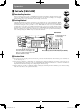
▋XBus▋Function【X.BUS】
▋▋Function▋Explanation
This XG14 has all new X-Bus system using JR's own serial bus data instead of PWM (Pulse Wide
Modulation) to communicate with X-Bus products such as servos. Control signals are sent in a
serial manner to all channels, with individual servos recognizing their own data from receiver.
※ It is required to use X-Bus capable receiver system in order to perform Serial data
transmission. X-Bus servos must be also programmed to be used on certain channels, other
wise it will not operate correctly.
▋▋Setting▋Method
There are two type of X- Bus available in the program.
M O D E . A : This is the JR’s own Original mode it corresponds to the X-Bus servo, Gyro system or able to
allocate Channel ID from the transmitter.
MODE.B: This is serial protocol mode it is corresponds to Freakware, Beast X and Mikado V-Bar ybarless
gyro systems.
Out putting channels are used as follows. Maximum channel is limited to 12channel for this application.
1) Aileron
2) Elevator
3) Rudder
4) AUX1 ((Pitch/Flap)
5) Throttle
6) GEAR
7) AUX2
8) AUX3
9) AUX4
10)AUX5
11)AUX6
12)AUX7
※ Note carefully that there will be “NO” PWM output signals from standard ports at the receiver when X.Bus has
been activated in MODE.B.
※ When using a DMSS Receivers without X.Bus capability BUS TYPE should be set to INH.
Helicopter
Airplane
DANGER
WARNING
CAUTION
Glider
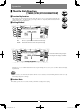
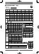
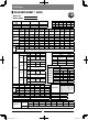
System▋List
Main ID on Left and Sub ID on
Right for compliant Device
which need to change ID.
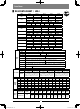
Main ID on Left and Sub ID on
Right for compliant Device.
Set the Cursor on the specific
item and Press the scroll dial
to finalize.
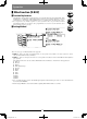
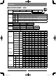
This is the value of the SETTING amount that
determines how precisely the servo moves for one
increment of increase-decrease. (similar to trim
step) It can be set between 1% - 10% with 1%
offering fine control and 10% coarse adjustment.
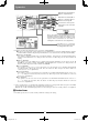
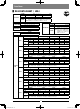
Press either “+” or “- to increase
or decrease the numerical value
on setting value in the center.
XG14English.indd 92 2013/07/16 16:41