
User's Manual


6. 3.
This equipment generates and uses radio frequency energy and if not installed and used properly,
that is, in strict accordance with the manufacture's instructions, may cause interference to radio and
television reception. It has been tested and found to comply with limits for a Class B digital device in
accordance with Part 15 of FCC Rules and CE I-ETS 300 440, which are designed to provide
reasonable protection against such interference in a residential installation. However, there is no
guarantee that interference will not occur in a particular installation. If this equipment does cause
interference to radio or television reception, which can be determined by turning the equipment off
and on, the user is encouraged to try to correct the interference by one or more of the following
measures:
1. Reorient the TV/radio antenna.
2. Relocate the Receiver away from the TV/radio receiver.
3. Plug the Receiver into a different wall outlet so that the Receiver is on a different branch circuit.
4. If necessary, the user should consult the dealer or an experienced radio/television technician
for additional suggestions.
The user may find the following booklet prepared by the Federal Communication Commission helpful:
"How to Identify and Resolve TV Interference Problems." This booklet is available from the US
Government Printing Office, Washington, D.C. 20402, Stock No. 004-000-00345-4.
FCC/CE NOTICE
The user is cautioned that changes or modifications not expressly approved by the manufacturer
could void the user's authority to operate the equipment. Linear radio controls provide a reliable
communications link and fill an important need in portable wireless signaling. However, there are
some limitations which must be observed. The radios are required to comply with FCC Rules and
Regulations as Part 15 devices and CE I-ETS 300 440. As such, they have limited transmitter
power and therefore limited range. A receiver cannot respond to more than one transmitted signal
at a time and may be blocked by radio signals that occur on or near their operating frequencies.
Changes or modifications to the device may void FCC and CE compliance. Infrequently used radio
links should be tested regularly to protect against undetected interference or fault
Operation is subject to the following two conditions:1) this device may not cause interference and
2) this device must accept any interference, including interference that may cause undesired operation
of the device.
FCC/CE WARNING
When installing the camera, check the reception of the receiver before final installation. Have someone
hold the camera in the area to be monitored. Have another person move the receiver to a variety of
locations throughout the house to check reception. If interference or other problems occur, refer to the
Troubleshooting Guide.
System Installation
To install the system, follow these steps:
- Select the channel (Channel 1-4, as indicated on Channel Label) to be used on both the camera
and receiver.
NOTE: Make sure the camera and receiver are set to the same channel (1, 2, 3, 4).
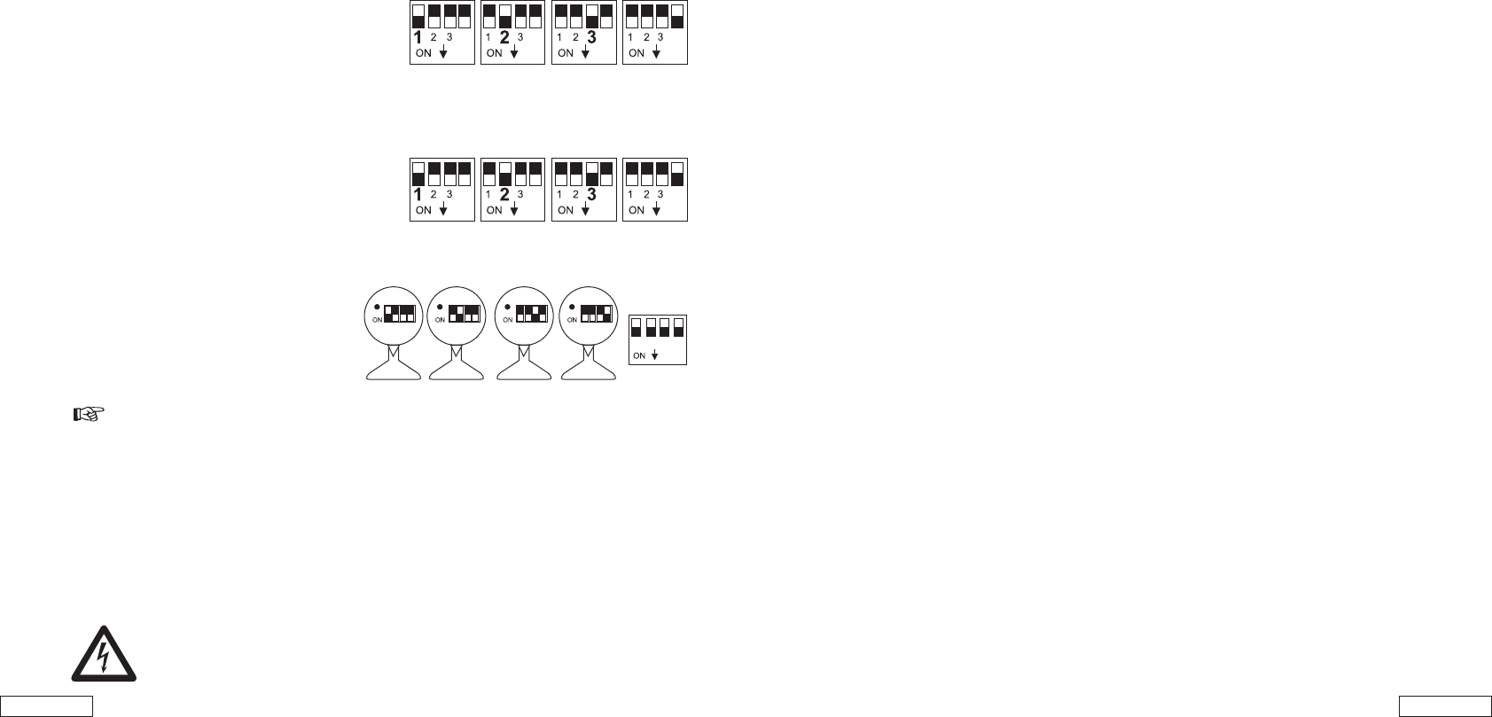
Channel selection on the camera
To set the channel selection switch on the camera, proceed as follows:
- To set the channel selection switch, please take a
pointed object, e.g. a ballpoint pen and select
the desired channel switch (no. 1 to no. 4) to position
"ON". The selected channel always remains active.
Only one channel may be activated at one time.
Channel selection on the receiver
The receiver can receive up to 4 radio cameras. You now have the possibility of selecting a
certain channel or monitoring up to 4 cameras in scan operation.
a) Manual channel selection:
To set the channel selection switch on the receiver,
please take a pointed object, e.g. a ballpoint
pen and select the desired channel switch
(no. 1 to no. 4) to position "ON" . The selected
channel always remains active.
b) Auto-scan mode:
If there are several (up to 4) cameras in operation,
you can allow the channels to run through
automatically (scan mode). For this only
switch over the desired channel which
you wish to monitor. The channels are
selected automatically one after another
The channel switch over time is approx.
5 seconds.
This feature is outstandingly suitable for monitoring up to 4 cameras
on one surveillance monitor.
If not all 4 channels are occupied with cameras, you have the possibility to block channels
which are not occupied (position "OFF") on both camera and receiver. These will simply be
left out in the auto-scan mode.
- The aerial of the radio camera can be adjusted to ensure the best possible transmission quality.
Please rotate them carefully so that they are vertical. The aerial can only be rotated within a
certain range. Do not rotate the aerials over and beyond the rotation limits with force as they
could be destroyed.
- Alter the channel set on the radio camera and on the receiver (channel selection switches and
if transmission is disturb,) see also "Elimination of disturbances".
- To switch off the devices, proceed in the opposite order to switching them off.
Always pull the plug-in power units out of the mains socket if not
used for a longer period.
Parts Included in This System
1. 2.4 GHz Wireless color camera
2. 2.4 GHz Wireless receiver
3. 7.5V AC/DC Adaptor for the camera
4. 7.5V AC/DC Adaptor for the Receiver
5. AV cable
6. 9V battery snap
1 2 3 4
1 2 3 4 1 2 3 4 1 2 3 4
Camera 1 Camera 2 Camera 3
1 2 3 4
Camera 4
Receiver
4 4 4
4
4 4 4
4