Network Xtreme Rack Tower Series (NXRT) User’s & Installation Manual Xtreme Power Conversion™ Corporation
NXRT‐1000, NXRT‐1500, NXRT‐2000, NXRT‐3000 USER’S MANUALUNINTERRUPTIBLE POWER SUPPLY (UPS) Table of Contents IMPORTANT SAFETY INSTRUCTIONS: ................................................. 4 INTRODUCTION........................................................................................... 6 PRODUCT DESCRIPTION .......................................................................... 6 SYSTEM CONFIGURATION........................................................................
NXRT‐1000, NXRT‐1500, NXRT‐2000, NXRT‐3000 USER’S MANUALUNINTERRUPTIBLE POWER SUPPLY (UPS) EMC Statements ‐ FCC Part 15 Notice: Pursuant to section 15 of the FCC rules, this product has been tested and thereby complies to the conditions of a Class B (NXRT‐1000, NXRT‐1500) and Class A (NXRT‐2000, NXRT‐3000) digital device, which have been established for offering sufficient protection against dangerous interference for installation in a residential area.
NXRT‐1000, NXRT‐1500, NXRT‐2000, NXRT‐3000 USER’S MANUALUNINTERRUPTIBLE POWER SUPPLY (UPS) IMPORTANT SAFETY INSTRUCTIONS: (SAVE THESE INSTRUCTIONS) CAUTION! (UPS having Internal Batteries): Risk of electrical shock – Hazardous live parts inside this unit are energized from the battery supply even when the input AC power is disconnected. CAUTION! (No User serviceable Parts): Risk of electrical shock, do not remove cover. No user serviceable parts inside. Refer servicing to qualified service personnel.
NXRT‐1000, NXRT‐1500, NXRT‐2000, NXRT‐3000 USER’S MANUALUNINTERRUPTIBLE POWER SUPPLY (UPS) CAUTION The unit has a dangerous amount of voltage. If the UPS indicator is on, the unit’s outlets may have a dangerous amount of voltage even when not plugged into the wall outlet because the battery may continue to supply power.
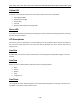
NXRT‐1000, NXRT‐1500, NXRT‐2000, NXRT‐3000 USER’S MANUALUNINTERRUPTIBLE POWER SUPPLY (UPS) INTRODUCTION The information provided in this manual covers single phase 1000‐3000 VA uninterruptible power systems, their basic functions, operating procedures, options available and emergency situations. It also includes information on how to ship, store, handle, and install the equipment.
NXRT‐1000, NXRT‐1500, NXRT‐2000, NXRT‐3000 USER’S MANUALUNINTERRUPTIBLE POWER SUPPLY (UPS) Figure 1 – Block Diagram Diagnostic Tests When the UPS is started, a diagnostic test is automatically executed, checking the electronics and batteries, reporting any problems on the LCD display. A diagnostic test can also be performed manually from the front panel at any time. SYSTEM CONFIGURATION The UPS device and the internal batteries make up the system.
NXRT‐1000, NXRT‐1500, NXRT‐2000, NXRT‐3000 USER’S MANUALUNINTERRUPTIBLE POWER SUPPLY (UPS) [8]
NXRT‐1000, NXRT‐1500, NXRT‐2000, NXRT‐3000 USER’S MANUALUNINTERRUPTIBLE POWER SUPPLY (UPS) LED Description The UPS has three LED’s on the front control panel. These LED’s allow the user to quickly understand if any action is needed. Red LED If this LED is illuminated it indicates a fault and the UPS will have no output.
NXRT‐1000, NXRT‐1500, NXRT‐2000, NXRT‐3000 USER’S MANUALUNINTERRUPTIBLE POWER SUPPLY (UPS) Yellow LED If this LED is illuminated it indicates the user needs to take some action, and included: • • • • • UPS in Bypass Mode Batteries Overcharged Charger fault Fan fault Batteries discharged to low voltage level Green LED If this LED is illuminated it indicates that everything is normal and the UPS is being powered by incoming AC utility or by the batteries.
NXRT‐1000, NXRT‐1500, NXRT‐2000, NXRT‐3000 USER’S MANUALUNINTERRUPTIBLE POWER SUPPLY (UPS) Line Four This indicates the status of the UPS. • • • • ON LINE = utility mode ON BATT = battery mode ON BPS = bypass mode UPS OFF = standby mode RS‐232 Standard Interface The RS‐232 interface uses a 9‐pin female D‐sub connector. Information provided includes data about utility, load and the UPS.
NXRT‐1000, NXRT‐1500, NXRT‐2000, NXRT‐3000 USER’S MANUALUNINTERRUPTIBLE POWER SUPPLY (UPS) Remote Emergency Power Off (REPO) Port A customer supplied switch located remotely can be used to open the REPO connection and allows the UPS output receptacles to be switched off. Since the REPO shuts down the equipment immediately, orderly shutdown procedures are not followed by any power management software. The UPS will have to be manually restarted in order to regain power to the outlets on the UPS.
NXRT‐1000, NXRT‐1500, NXRT‐2000, NXRT‐3000 USER’S MANUALUNINTERRUPTIBLE POWER SUPPLY (UPS) Please handle the UPS and associated equipment with extreme caution since a high amount of energy is contained in the batteries. Always keep the unit in an upright position as marked on the packaging, and never drop the unit. Please adhere to the following instructions if the UPS is not installed immediately: • • • Store the equipment as is in its original packing and shipping carton.
NXRT‐1000, NXRT‐1500, NXRT‐2000, NXRT‐3000 USER’S MANUALUNINTERRUPTIBLE POWER SUPPLY (UPS) Installation Standard brackets [14]
NXRT‐1000, NXRT‐1500, NXRT‐2000, NXRT‐3000 USER’S MANUALUNINTERRUPTIBLE POWER SUPPLY (UPS) 19” Cabinet Ear Installation [15]
NXRT‐1000, NXRT‐1500, NXRT‐2000, NXRT‐3000 USER’S MANUALUNINTERRUPTIBLE POWER SUPPLY (UPS) Vertical Installation Steps [16]
NXRT‐1000, NXRT‐1500, NXRT‐2000, NXRT‐3000 USER’S MANUALUNINTERRUPTIBLE POWER SUPPLY (UPS) Wall‐mounted Installation Steps [17]
NXRT‐1000, NXRT‐1500, NXRT‐2000, NXRT‐3000 USER’S MANUALUNINTERRUPTIBLE POWER SUPPLY (UPS) 19” Rack mount using 5 in 1 bracket [18]
NXRT‐1000, NXRT‐1500, NXRT‐2000, NXRT‐3000 USER’S MANUALUNINTERRUPTIBLE POWER SUPPLY (UPS) RACKMOUNT INSTALLATION STEPS UPS Rail Installation Instructions to 19” Cabinet 1. 2. 3.
NXRT‐1000, NXRT‐1500, NXRT‐2000, NXRT‐3000 USER’S MANUALUNINTERRUPTIBLE POWER SUPPLY (UPS) 4. 5.
NXRT‐1000, NXRT‐1500, NXRT‐2000, NXRT‐3000 USER’S MANUALUNINTERRUPTIBLE POWER SUPPLY (UPS) 6. 7. Note: Any external Battery Packs must be installed next to or under the UPS. Please refer to Appendix A: Battery Pack User Guide for more information when installing these.
NXRT‐1000, NXRT‐1500, NXRT‐2000, NXRT‐3000 USER’S MANUALUNINTERRUPTIBLE POWER SUPPLY (UPS) INITIAL CONNECTION AND STARTUP: Ensure that the UPS and optional battery packs are mounted correctly, and the UPS is disconnected from input power before proceeding. 1. Connect external battery packs (option) CAUTION: CONNECT ONLY BATTERY PACKS PROVIDING THE SAME DC VOLTAGE AS THE UPS – PLEASE DOUBLE CHECK LABELING ON THE UPS AND BATTERY PACKS TO ASSURE PROPER VOLTAGES ARE CONNECTED.
NXRT‐1000, NXRT‐1500, NXRT‐2000, NXRT‐3000 USER’S MANUALUNINTERRUPTIBLE POWER SUPPLY (UPS) 6. Start and configure the UPS On/Off Button Function Button Inquiry Button • Press and hold the ON/OFF button for more than 3 seconds to turn on the UPS. The UPS should now start its inspection of the internal functions, main synchronization, and inverter startup. Then power should start to be supplied via the outlets.
NXRT‐1000, NXRT‐1500, NXRT‐2000, NXRT‐3000 USER’S MANUALUNINTERRUPTIBLE POWER SUPPLY (UPS) • NOTE: PLEASE VERIFY AUTOMATIC SHUTDOWN TIME PARAMETERS IN THE SETTINGS SECTION FOR YOUR SPECIFIC INSTALLATION. 9. After charging is complete, connect the loads to the UPS while monitoring the load levels via the UPS LCD or via the software. • Do not connect any devices that have the possibility of overloading the UPS. Refer to the Troubleshooting section and/or Technical Support with any problems during setup.
NXRT‐1000, NXRT‐1500, NXRT‐2000, NXRT‐3000 USER’S MANUALUNINTERRUPTIBLE POWER SUPPLY (UPS) • Once turned on, the UPS will perform a self‐test function, when the yellow LED turns to green, LCD displays “On Batt” – the UPS is now functioning in DC mode. Turning Off the UPS when in DC Mode • • Press and hold the ON/OFF button for more than 3 seconds to turn off the UPS. This means the internal inverter has been deactivated. During the shutdown period, the UPS will run a self test.
NXRT‐1000, NXRT‐1500, NXRT‐2000, NXRT‐3000 USER’S MANUALUNINTERRUPTIBLE POWER SUPPLY (UPS) BATTERIES The life of batteries used in these UPS products is estimated at 3‐6 years depending on level of usage. Once the battery is no longer useful and must be replaced, please contact service personnel for assistance. REPLACING THE BATTERY (QUALIFIED SERVICE PERSONNEL ONLY) CAUTION! Read and follow the IMPORTANT SAFETY INSTRUCTIONS before servicing the battery.
NXRT‐1000, NXRT‐1500, NXRT‐2000, NXRT‐3000 USER’S MANUALUNINTERRUPTIBLE POWER SUPPLY (UPS) Slide the plastic cover to the right. Remover the M5x10 screws on the right side.
NXRT‐1000, NXRT‐1500, NXRT‐2000, NXRT‐3000 USER’S MANUALUNINTERRUPTIBLE POWER SUPPLY (UPS) Remove (4) M4x6 screws marked with letter A. Remove the battery tray from the UPS.
NXRT‐1000, NXRT‐1500, NXRT‐2000, NXRT‐3000 USER’S MANUALUNINTERRUPTIBLE POWER SUPPLY (UPS) TROUBLESHOOTING Issue Audible Alarm Alarm Description What You Should Do The “Input” letters in the second row of the LCD are flashing The “Input” letters in the second row of the LCD are flashing Two Beeps per second at startup for 8 total seconds One beep per 2 minutes Possible mis‐wiring AC line and neutral line Check wiring of input to UPS (reversed wiring, etc) Rewire, if necessary Battery Indicator Flas
NXRT‐1000, NXRT‐1500, NXRT‐2000, NXRT‐3000 USER’S MANUALUNINTERRUPTIBLE POWER SUPPLY (UPS) LCD FAULT CODES BYP MODE LINE MODE BAT MODE BAT TEST MODE BUS FAULT 62 05、25 01、21 40、41 INV FAULT 61、63 04 24 42 33 / / 36 07 11 06 16 03 28 07 11 08 02 09 38 / 11 43 44 45 46 / 11 OVERHEAT OP SHORT OVERLOAD FAN FAULT CHARGE FAULT BAT OVER [30]
NXRT‐1000, NXRT‐1500, NXRT‐2000, NXRT‐3000 USER’S MANUALUNINTERRUPTIBLE POWER SUPPLY (UPS) SPECIFICATIONS 120V MODEL INPUT NXRT-1000 Voltage Capacity VA (W) NXRT-1500 1000 VA (700 W) 1500 VA (1050 W) True on-line, Double conversion, Input PF correction Voltage 120 VAC Frequency 50/60 Hz auto sensing THD (full load) Linear ≤ 5%; non-Linear ≤ 10% Wave Form Sine wave, zero transfer time Load Power Factor 0.7 Efficiency AC/DC/AC ≥90% Auto Restart Yes Start on Battery Yes 8.3 A 12.
NXRT‐1000, NXRT‐1500, NXRT‐2000, NXRT‐3000 USER’S MANUALUNINTERRUPTIBLE POWER SUPPLY (UPS) 120V MODEL PHYSICAL Dimensions NXRT-1500 NXRT-2000 W x D x H (inches) NXRT-3000 W x D x H (inches) Unit Dimensions 17.3" x 17.7" x 3.4" 17.3" x 25.6" x 3.4" 17.3" x 21.7" x 5.2" Shipping Dimensions 22.3" x 23.5" x 9.2" 22.3" x 31.4" x 9.2" 22.3" x 27.4" x 11.0" Unit Weight 39.7 lbs 57.3 lbs 79.4 lbs 81.6 lbs Shipping Weight 50.7 lbs 68.4 lbs 91.5 lbs 93.
NXRT‐1000, NXRT‐1500, NXRT‐2000, NXRT‐3000 USER’S MANUALUNINTERRUPTIBLE POWER SUPPLY (UPS) EXTENDED BATTERY PACK MODELS INPUT NXRT-EBP1 NXRT-EBP2 Voltage AC Current 120 VAC 1.5A 2.2A Frequency DC Voltage 4A 50/60 Hz auto sensing Input Protection CHARGER OUTPUT NXRT-EBP3 resettable circuit breaker 41.2 ±0.5V 55.0 ±0.5V DC Current 110.0 ±0.5V 2.
NXRT‐1000, NXRT‐1500, NXRT‐2000, NXRT‐3000 USER’S MANUALUNINTERRUPTIBLE POWER SUPPLY (UPS) SHIPPING LIST 1. 2. 3. 4. 5. 6.
NXRT‐1000, NXRT‐1500, NXRT‐2000, NXRT‐3000 USER’S MANUALUNINTERRUPTIBLE POWER SUPPLY (UPS) OBTAINING SERVICE If the UPS requires Service: 1. Use the TROUBLESHOOTING section in this manual to eliminate obvious causes. 2. Verify there are no circuit breakers tripped. 3. Call your dealer for assistance. If you cannot reach your dealer, or if they cannot resolve the problem, call Xtreme Power Conversion Corp Technical Support at 800.582.4524. Technical support inquires can also be made at support@xpcc.com.
NXRT‐1000, NXRT‐1500, NXRT‐2000, NXRT‐3000 USER’S MANUALUNINTERRUPTIBLE POWER SUPPLY (UPS) XTREME POWER CONVERSION™ (XPC) CORPORATION LIMITED WARRANTY Xtreme Power Conversion (XPC) Corporation warrants Xtreme Power Conversion equipment, when properly applied and operated within specified conditions, against faulty materials or workmanship (excluding batteries) for a period of three years for NXRT‐Series products from the date of purchase.
NXRT‐1000, NXRT‐1500, NXRT‐2000, NXRT‐3000 USER’S MANUALUNINTERRUPTIBLE POWER SUPPLY (UPS) APPENDIX A: EXTENDED BATTERY PACK USER GUIDE Estimated Run Time for UPS with Extended Battery Packs MODEL NXRT‐ 1000 NXRT‐ 1500 NXRT‐ 2000 NXRT‐ 3000 LOAD VA WATTS 500 350 1000 700 750 525 1500 1050 1000 700 2000 1400 1500 1050 3000 2100 RUNTIME FOR QTY OF EXTENDED BATTERY PACKS IN MIN.
NXRT‐1000, NXRT‐1500, NXRT‐2000, NXRT‐3000 USER’S MANUALUNINTERRUPTIBLE POWER SUPPLY (UPS) CAUTION: It is very critical to connect the correct voltage EBP with the UPS intended. EBP1 is for NXRT‐1000 EBP2 is for NXRT‐1500 EBP3 is for NXRT‐2000/3000 CONNECTING THE INCORRECT BATTERY PACK TO THE UPS MAY RESULT IN DAMAGE TO THE UPS AND/OR BATTERY PACK WILL VOID THE WARRANTY. All EBP’s have a different DC voltage configuration intended only for the UPS’s listed above.
NXRT‐1000, NXRT‐1500, NXRT‐2000, NXRT‐3000 USER’S MANUALUNINTERRUPTIBLE POWER SUPPLY (UPS) Extended Battery Pack Configuration [39]
NXRT‐1000, NXRT‐1500, NXRT‐2000, NXRT‐3000 USER’S MANUALUNINTERRUPTIBLE POWER SUPPLY (UPS) [40]
NXRT‐1000, NXRT‐1500, NXRT‐2000, NXRT‐3000 USER’S MANUALUNINTERRUPTIBLE POWER SUPPLY (UPS) LED Description The Charging LED GREEN indicates that the battery charger in the Extended Battery Pack is charging normally with the AC power cord attached to the Battery pack. The Battery Test LED GREEN indicates that the DC output of the Extended Battery Pack (EBP) is normal.
NXRT‐1000, NXRT‐1500, NXRT‐2000, NXRT‐3000 USER’S MANUALUNINTERRUPTIBLE POWER SUPPLY (UPS) 2. The EBP’s use a cable shipped with each EBP to “daisy chain” together additional EBP’s to the first EBP being connected to the UPS in the appropriately labeled connector, or for connecting the first EBP to the UPS. 3. The AC input cord is for connecting AC utility to operate the Charger contained in each EBP.
NXRT‐1000, NXRT‐1500, NXRT‐2000, NXRT‐3000 USER’S MANUALUNINTERRUPTIBLE POWER SUPPLY (UPS) 4. The input AC Circuit Breaker will trip to the OFF position in the event that the internal EBP charger draws excessive current. Extended Battery Pack Installation CAUTION: Extended Battery Pack (EBP) Installation should be performed by qualified service personnel. 1. Verify that the DC circuit breaker on the rear panel of the EBP is in the OFF position. 2.
NXRT‐1000, NXRT‐1500, NXRT‐2000, NXRT‐3000 USER’S MANUALUNINTERRUPTIBLE POWER SUPPLY (UPS) 5. Secure the DC battery cable to both the rear of the UPS and the rear of the EBP by using M3 x 8 screws provided (2 each per connector end). 6. Repeat the above procedure for testing and securing each additional EBP required. CAUTION: Do not use extension cords when connecting input AC power to UPS or EBP’s 7. Move the DC circuit breaker on the rear of each EBP to the ON position.
NXRT‐1000, NXRT‐1500, NXRT‐2000, NXRT‐3000 USER’S MANUALUNINTERRUPTIBLE POWER SUPPLY (UPS) 5. Why don’t the LED’s on each EBP connected to an AC input source turn ON and OFF at the same time? • The charger on each EBP functions independently from the others. One EBP charger may be charging while another one might be at 100% and the charger turned off. This is normal operation of the EBP.