ENGLISH DDL-8700 Instruction Manual
CONTENTS 1. SPECIFICATIONS........................................................................................................1 2. INSTALLATION...........................................................................................................1 3. INSTALLING THE BELT COVER AND THE BOBBIN WINDER................................2 4. ADJUSTING THE HEIGHT OF THE KNEE LIFTER...................................................2 5. INSTALLING THE THREAD STAND..............................................
1. SPECIFICATIONS DDL-8700 Application DDL-8700A DDL-8700H Sewing speed General fabrics, light-weight and medium-weight materials Max. 5,500 sti/min General fabris, light-weight materials Max. 4,000 sti/min Medium-weight materials, heavy-weight materials Max. 4,000 sti/min Needle DB x 1 #9 to #18 (134 #65 to #110) DA x 1 #9 to #11 (134 #65 to #75) DB x 1 #20 to #23 (134 #125 to #160) Stitch length Max. 5 mm Presser foot lift (by knee lifter) Lubricating oil 10 mm (Standard) 13 mm (Max.) Max.
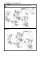
3. INSTALLING THE BELT COVER AND THE BOBBIN WINDER WARNING : To protect against possible personal injury due to abrupt start of the machine, be sure to start the following work after turning the power off and ascertaining that the motor is at rest. (mm) (mm) (DDL-8700L) 62 62 33 33 47 63.5 75.5 63.5 75.5 4.
. INSTALLING THE THREAD STAND 6. LUBRICATION WARNING : To protect against possible personal injury due to abrupt start of the machine, be sure to start the following work after turning the power off and ascertaining that the motor is at rest. (1) Information on lubrication 1) Fill oil pan 1 with JUKI New Defrix Oil No. 1 up to HIGH mark A. 2) When the oil level lowers below LOW mark B, refill the oil pan with the specified oil.
7. ADJUSTING THE AMOUNT OF OIL (OIL SPLASHES) IN THE HOOK WARNING : Be extremely careful about the operation of the machine since the amount of oil has to be checked by turning the hook at a high speed. 2 Position to confirm the amount of oil (oil splashes) 25 mm 3 - 10 mm 1 Amount of oil (oil splashes) confirmation paper 70 mm Oil splashes confirmation paper * 1) 2) 3) 4) Closely fit the paper against the wall surface of the bed.
8. ATTACHING THE NEEDLE WARNING : To protect against possible personal injury due to abrupt start of the machine, be sure to start the following work after turning the power off and ascertaining that the motor is at rest. 9. SETTING THE BOBBIN INTO THE BOBBIN CASE 1) Pass the thread through thread slit A, and pull the thread in direction B. By so doing, the thread will pass under the tension spring and come out from notch B.
11. PRESSER FOOT PRESSURE 29 - 32 mm 12. HAND LIFTER 13. ADJUSTING THE HEIGHT OF THE PRESSER BAR WARNING : To protect against possible personal injury due to abrupt start of the machine, be sure to start the following work after turning the power off and ascertaining that the motor is at rest. 1 1) Loosen setscrew 1, and adjust the presser bar height or the angle of the presser foot. 2) After adjustment, securely tighten the setscrew 1.
14. THREADING THE MACHINE HEAD WARNING : To protect against possible personal injury due to abrupt start of the machine, be sure to start the following work after turning the power off and ascertaining that the motor is at rest.
15. THREAD TENSION (1) Adjusting the needle thread tension 1) As you turn thread tension nut 1 clockwise (in direction A), the needle thread tension will be increased. 2) As you turn nut 1 counterclockwise (in direction B), the needle thread tension will be decreased. C (2) Adjusting the bobbin thread tension D 2 1 1) As you turn tension adjust screw 2 clockwise (in direction C), the bobbin thread tension will be increased.
18. NEEDLE-TO-HOOK RELATIONSHIP WARNING : To protect against possible personal injury due to abrupt start of the machine, be sure to start the following work after turning the power off and ascertaining that the motor is at rest. (1) Adjust the timing between the needle and the hook as follows : C 1 D A B 0.04 - 0.1 mm 4 5 3 A B 2 a 1) Turn the handwheel to bright the needle bar down to the lowest point of its stroke, and loosen setscrew 1.
20. TILT OF THE FEED DOG WARNING : To protect against possible personal injury due to abrupt start of the machine, be sure to start the following work after turning the power off and ascertaining that the motor is at rest. A B 1) The standard tilt (horizontal) of the feed dog is obtained when marker dot A on the feed bar shaft is aligned with marker dot B on feed rocker 1. (DDL-8700H, the marker dot B inclines forward the feed rocker shaft by 90˚, as standard).
22. ADJUSTING THE FEED TIMING (DDL-8700L) WARNING : To protect against possible personal injury due to abrupt start of the machine, be sure to start the following work after turning the power off and ascertaining that the motor is at rest. 3 2 Standard feed timing B Advanced feed timing A 1 Delayed feed timing 1) Tilt the machine head and insert a screwdriver from the bottom side of the machine head.
23. MOTOR PULLEYS AND BELTS 1) A clutch motor with 400W output (1/2 HP) is used as the standard motor. 2) An M-type V belt should be used. 3) The relationship between the motor pulleys, belt lengths and sewing speeds is shown in the following table : Sewing speed (rpm) Motor pulley O.D. (mm) Motor pulley part No.