Operating Manual Recirculating Cooler F250 F500 F1000 Original Operating Manual 1.951.4806-V1 08/14 Proj. 1789 JULABO GmbH 77960 Seelbach / Germany Tel. +49 (0) 7823 / 51-0 Fax +49 (0) 7823 / 24 91 info@julabo.de www.julabo.
Congratulations! You have made an excellent choice. JULABO thanks you for the trust you have placed in us. This operating manual has been designed to help you gain an understanding of the operation and possible applications of our circulators. For optimal utilization of all functions, we recommend that you thoroughly study this manual prior to beginning operation.
F250, F500, F1000 CONTENT 1. Intended use ................................................................................................................4 2. Operator responsibility – Safety recommendations .......................................................4 3. Handling.........................................................................................................................5 3.1. Appropriate operation ....................................................................................
Intended use 1. Intended use JULABO recirculating coolers have been designed for temperature application to specific fluids. The pump connections can be used for cooling applications in an external circuit at a constant temperature. The recirculating coolers are operated via the splash-proof keypad. The implemented microprocessor technology allows to set and to store the setpoint that can be indicated on the LED temperature display.
F250, F500, F1000 If you have any questions concerning the operation of your unit or the information in this manual, please contact us! Contact: JULABO GmbH Eisenbahnstraße 45 77960 Seelbach / Germany +49 7823 51-0 +49 7823 2491 info@julabo.de www.julabo.de 3. Handling You have received a product designed for industrial use. Nevertheless, avoid strikes to the housing, vibrations, damage to the operating-element panel (keypad, display), and contamination.
Handling well ventilated areas. The unit is not for use in explosive atmosphere. Only use recommended materials (bath fluids). Only use non-acid and non corroding materials. When using hazardous materials or materials that could become hazardous, the operator must affix the enclosed safety labels (1 + 2) to the front of the unit so they are highly visible: 1 Danger area. Attention! Observe instructions.
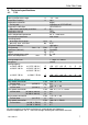
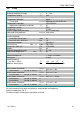
F250, F500, F1000 4. Technical specifications 4.1. F250 Recirculating Cooler Working temperature range Temperature stability Temperature selection: via key pad Temperature indication: Adjustment and display resolution Temperature control Temperature sensor Excess temperature protection Low liquid level protection Circulating pump: discharge, max.at 0 bar pressure, max. at 0 Liters Filling level indicator Filling volume from ...
Technical specifications 4.2. F500 Recirculating Cooler Working temperature range Temperature stability °C °C Temperature selection: via key pad Temperature indication: Adjustment and display resolution Temperature control Temperature sensor Excess temperature protection Low liquid level protection Circulating pump: discharge, max.at 0 bar pressure, max. at 0 Liters Filling level indicator Filling volume Dimensions (WxLxH) Weight Ambient temperature range Return flow temperature °C l/min bar from ...
F250, F500, F1000 4.3. F1000 Recirculating Cooler Working temperature range Temperature stability °C °C Temperature selection: via key pad Temperature indication: Adjustment and display resolution Temperature control Temperature sensor Excess temperature protection Low liquid level protection Circulating pump: discharge, max.at 0 bar pressure, max. at 0 Liters Filling level indicator Filling volume Dimensions (WxLxH) Weight Ambient temperature range Return flow temperature °C l/min bar from ...
Technical specifications 4.4. Warning functions and safety installations Excess temperature protection Low liquid level protection Alarm messages Overload protection Classification according to DIN 12876-1 85 °C - fixed value float switch optical + audible (permanent) for compressor and pump motor Class I Environmental conditions according to IEC 61 010-1: - Use only indoor. - Altitude up to 2000 m - normal zero. - Ambient temperature: +5 ... +40 °C - Air humidity: - Max. rel.
F250, F500, F1000 4.5. Materials of Construction of the wetted Parts Designation Tube, inner diameter 8.0 x 2.0 mm Sealings processed F250 Material PVC PA Bath, complete Sealing screw a.f. 13.0 x 11.0 Profile sealing 1.4404, 1.4301, 1.4435 1.4571 Silicone, white Filling pipe, above Stopper O-ring PVC POM CR11-70 (Chloroprene rubber) Motor mounting sheet Motor plate Pump Sensors 2xPt 100 Float switch 1.4301 1.4301, 1.4401, PPS (Rytone) 1.4571 1.
Designation Tube (level indicator) Sealings processed F1000 Material PVC PA Bath, complete Sealing screw a.f. 13.0 x 11.0 Profile sealing 1.4301, 1.4404 1.4571 Cellular rubber,neoprene 4.314.9910 Filling pipe, above Stopper O-ring PVC, gray POM CR11-70 (Chloroprene rubber) Motor mounting sheet Motor plate Pump Sensors 2xPt 100 Float switch 1.4301/304H,1.4305/303 1.4301/304H, EPDM, 1.4401, PTFE, FKM 1.4571 1.4301, PP Barbed fittings 1.4305/303 12 1.951.
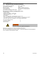
F250, F500, F1000 5. Safety Notes 5.1. Description of the safety notes In addition to the safety warnings listed, warnings are posted throughout the manual. These warnings are designated by an exclamation mark inside an equilateral triangle. “Warning of a dangerous situation (Attention! Please follow the documentation).” The danger is classified using a signal word. Read and follow these important instructions. indicates a hazardous situation which, if not avoided, will result in death or serious injury.
Safety Notes 5.3. Safety instructions Follow the safety recommendations to prevent damage to persons or property. Further, the valid safety instructions for working places must be followed. • Only connect the unit to a power socket with earthing contact (PE – protective earth)! • The power supply plug serves as a safe disconnecting device from the line and must always be easily accessible. • Place the instrument on an even surface on a pad made of non-inflammable material.
F250, F500, F1000 6. Moving up and connect Risk of injury for hands. Close cover carefully. Carry the unit with 2 persons. Wear safety shoes. 6.1. Transportation and site conditions F250 Caster platform (Order No.: 8910045 F500, F1000 Transport 1.951.4806-V1 • Lifting and Transport: At F250: Lift the unit with two persons taking hold of its bottom plate. For transport set the unit on a suitable caster platform (Order No.: 8910045).
Moving up and connect 6.2. Tubing Damage caused by leaking bath fluid! • Employ suitable connecting tubing • Make sure that the tubing is securely attached. • Avoid sharp bends in the tubing, and maintain a sufficient distance from surrounding walls. • Regularly check the tubing for material defects (e.g. for cracks). • Preventive maintenance: Replace the tubing from time to time.
F250, F500, F1000 F250 • • • F500, F1000 • • 1.951.4806-V1 Before operating the unit after transport, wait about one hour after installation. This will allow any oil that has accumulated laterally during transport to flow back down, thus ensuring that the compressor can develop its maximum capacity. Remove cap screws from the connections. Connect the tubing from the external system to the pump connectors and check for leaks.
Operating controls and functional elements 7. Operating controls and functional elements 7.1. F250 1 Main switch, splash water proofed with integral MCB. I = On O = Off 2 Indication elements 2(1) - LED Temperature display 2(2) - Control display “Cooling” 2(3) - Control display „Alarm“ 3 Foil key pad, splash water proofed 3.1 - Modify keys for Setpoint – higher / lower 3.2 - Enter key for storage of Setpoint / Parameter 4 5 Level indication Filling hole 18 1.951.
F250, F500, F1000 6 Power cable with plug 7 Pump connection - outlet, M10x1 male or barbed fitting ∅ 8/10 mm inner diameter 8 Pump connection - return, M10x1 male or barbed fitting ∅ 8/10 mm inner diameter 9 Overflow for Bath, Dout 10 mm, dinner 8 mm 10 Drain screw, M10x1 male 1.951.
Operating controls and functional elements 7.2. F500, F1000 1 Main switch, splash water proofed with integral MCB. I = On O = Off 2 Indication elements 2(1) - LED Temperature display 2(2) - Control display “Cooling” 2(3) - Control display „Alarm“ 3 Foil key pad, splash water proofed 3(1) - Modify keys for Setpoint – higher / lower 3(2) - Enter key for storage of Setpoint / Parameter 4 5 6 Level indication Filling hole Hand grip 20 1.951.
F250, F500, F1000 7 Power cable with plug 8 Pump connection - outlet, M16x1 male or barbed fitting ∅ 8/12 mm inner diameter. 9 Pump connection - return, M16x1 male or barbed fitting ∅ 8/12 mm inner diameter. 10 Overflow for Bath, Dout 10 mm, dinner 8 mm 11 Hand grip 12 Drain screw, M10x1 male 1.951.
Operating procedures 8. Operating procedures 8.1. Bath fluids No liability for use of other bath liquids! Please contact JULABO before using other than recommended bath fluids. JULABO takes no responsibility for damages caused by the selection of an unsuitable bath fluid Do not use alcohols. Water: The quality of water depends on local conditions. • Due to the high concentration of lime, hard water is not suitable for temperature control because it leads to calcification in the bath.
F250, F500, F1000 8.2. Power connection Danger of electric shock! • Only connect the unit to a power socket with earthing contact (PE – protective earth)! We disclaim all liability for damage caused by incorrect line voltages! • The power supply plug serves as safe disconnecting device from the line and must be always easily accessible. • Never operate equipment with damaged mains power cables. • Regularly check the mains power cables for material defects (e.g. for cracks).
Operating procedures 8.4. Switching on / Start - Stop Switching on: • The recirculating cooler is turned on and off with the mains switch (1). The unit performs a self-test. All segments of the 4-digit LED temperature DISPLAY and all indicator lights will illuminate Then the software version and the type of unit is indicated. The display "OFF" indicates the unit is ready to operate (standby mode). 8.5. Start: Press enter for about 4 seconds.
F250, F500, F1000 8.6. Timer function With the timer function the operating time can be limited to an allowed time. 8.6.1. Setting the time The setting can only be made in the Stop status. 1. Factory setting is the max. adjustable time: Calling the timer function: Hold the key pressed and activate the edit key shortly. The time which was set last, is shown. 2. Setting the time: 33 h 19 min. Activate key to set a higher value. Activate key to set a lower value.
Operating procedures 8.7. AUTOSTART ON / OFF The recirculating cooler has been configured and supplied by JULABO according to N.A.M.U.R. recommendations. This means for the start mode, that the unit must enter a safe operating state after a power failure (non-automatic start mode). This safe operating state is indicated by „OFF“ on the LED temperature display. A complete shutdown of the main functional elements such as compressor and circulating pump is effected simultaneously.
F250, F500, F1000 9. Safety installations 9.1. Excess temperature protection + This safety installation is independent of the control circuit. When the temperature of the bath fluid has reached the safety temperature (85 °C), a complete shutdown of the compressor and pump is effected. The alarm is indicated by optical and audible signals (continuous tone) and on the LED-DISPLAY appears the error message "Error 14". Check the sizing of the application. You may have to use a more powerful chiller.
Troubleshooting guide / Error messages 10. Troubleshooting guide / Error messages + Whenever the microprocessor electronics registers a failure, a complete shutdown of the compressor and circulating pump is performed. The alarm light " " illuminates and a continuous signal tone sounds. The LED temperature display indicates the cause for the alarm in form of a code. Press enter to quit the audible signal. • The recirculating cooler is operated without bath fluid, or the liquid level is insufficient.
F250, F500, F1000 • Switch off the unit • Wait for approx.2 seconds • Switch on the unit If the error occurs again, a remote diagnosis must be made. If the unit cannot be returned to operation, contact an authorized JULABO service station. Disturbances that are not indicated. Overload protection: a) for cooling machine b) for pump motor After a short cooling interval, the unit will automatically start running. (1) 1.951.4806-V1 Main fuse: The main switch (1) of the device is also a circuit breaker.
Cleaning / repairing the unit 11. Cleaning / repairing the unit Danger of electric shock! • Always turn off the unit and disconnect the mains cable from the power source before cleaning the unit. • Prevent humidity from entering into the circulator. • Electrical connections and any other work must be performed by qualified personnel only. Venting grid (front) To maintain the full cooling performance, clean the condenser from time to time. F250 1. Switch off the unit 2. disconnect mains power cable. 3.
F250, F500, F1000 When returning the unit: • Clean the unit in order to avoid any harm to the service personnel. • Package the unit carefully and properly. • Always include a brief description of the problem. If you send your JULABO unit back to us, please include a Service Return Note, which you can download at our website www.julabo.de. Please fill out the form and include it with the device or fax or e-mail it to us in advance. • The unit must be standing upright during shipment.
Warranty conditions 12. Warranty conditions JULABO GmbH warrants its products against defects in material or in workmanship, when used under appropriate conditions and in accordance with appropriate operating instructions for a period of ONE YEAR. Extension of the warranty period – free of charge With the ‘1PLUS warranty’ the user receives a free of charge extension to the warranty of up to 24 months, limited to a maximum of 10 000 working hours.
F250, F500, F1000 12.1. EC-Declaration of Conformity 12.1.1. F250 1.951.
Warranty conditions 12.1.2. 34 F500 1.951.
F250, F500, F1000 12.1.3. F1000 1.951.