English Operating manual Recirculating Coolers FL1201 FL1203 FL1701 FL1703 1.951.4822-V2 19514822-V2.doc 10/13 RS232 ALARM FL1203 FLW1701 FLW1703 Druck: 08.10.2013 JULABO GmbH 77960 Seelbach / Germany Tel. +49 (0) 7823 / 51-0 Fax +49 (0) 7823 / 24 91 info@julabo.de www.julabo.
Congratulations! You have made an excellent choice. JULABO thanks you for the trust you have placed in us. This operating manual has been designed to help you gain an understanding of the operation and possible applications of our circulators. For optimal utilization of all functions, we recommend that you thoroughly study this manual prior to beginning operation.
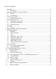
TABLE OF CONTENTS 1. Intended use ................................................................................................................................. 4 1.1. Description ........................................................................................................................ 4 2. Operator responsibility – Safety instructions ................................................................................ 4 2.1. Disposal ............................................................
1. Intended use JULABO recirculating coolers have been designed for temperature application to specific fluids. The pump connections can be used for cooling applications in an external circuit at a constant temperature. JULABO water baths are not suitable for direct temperature control of foods, semiluxury foods and tobacco, or pharmaceutical and medical products. Direct temperature control means unprotected contact of the object with the bath medium (bath fluid). 1.1.
Safety recommendations for the operator You received a product conceived for industrial use. Nevertheless, avoid strikes to the housing, vibrations, damages to the keypad foil (keys, display) or contamination. Make sure the product is regularly checked for proper condition. Regularly check (at least every 2 years) the proper condition of the mandatory, warning, prohibition and safety labels.
2.1. Disposal This unit contains the refrigerant R404A – at this time considered not to have any negative effects on the ozone layer. However, during the long operating period of the unit, disposal prescriptions may change. So only qualified personnel should take care of disposal. Valid in EU countries See the current official journal of the European Union – WEEE directive. Directive of the European Parliament and of the Council on waste electrical and electronic equipment (WEEE).
2.2.
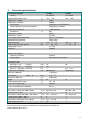
3. Technical specifications Recirculating Cooler Cooling Working temperature range Temperature stability Temperature selection: via key pad remote control via personal computer Temperature indication: Resolution Temperature control Temperature sensor Excess temperature protection Low liquid level protection Cooling capacity Medium: Mixture water-glycol Cooling compressor Refrigerant °C °C °C °C kW Electrical connections: Computer interface Alarm output Circulating pump: discharge, max.
Recirculating Cooler Cooling Working temperature range Temperature stability Temperature selection: via key pad remote control via personal computer Temperature indication: Resolution Temperature control Temperature sensor Excess temperature protection Low liquid level protection Cooling capacity Medium: Mixture water-glycol Cooling compressor Refrigerant °C °C °C °C kW FL1701 FLW1701 air cooled water cooled -20 ... +40 -20 ... +40 ±0.
Recirculating Cooler Cooling Working temperature range Temperature stability Temperature selection: via key pad remote control via personal computer Temperature indication: Resolution Temperature control Temperature sensor Excess temperature protection Low liquid level protection Cooling capacity Medium: Mixture water-glycol Cooling compressor Refrigerant °C °C °C °C kW FL1703 FLW1703 air cooled water cooled -20 ... +40 -20 ... +40 ±0.
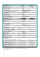
Warning functions and safety installations Excess temperature protection Low liquid level protection Alarm message Excess temperature - Warning function Overload protection Classification according to DIN 12876-1 85 °C - fixed value float switch optical + audible (permanent) 75 °C for compressor and pump motor class I Environmental conditions according to IEC 61 010-1: Use only indoor. Altitude up to 2000 m - normal zero. Ambient temperature: +5 ... +40 °C Air humidity: Max. rel.
3.1. Cooling water connection Only for water cooled models - FLW: Cooling water pressure (IN / OUT ) Difference pressure (IN - OUT ) Flow rate Cooling water temperature max.
4. 4.1. Safety notes for the user Explanation of safety notes In addition to the safety warnings listed above, warnings are posted throughout the manual. These warnings are designated by an exclamation mark inside an equilateral triangle. “Warning of a dangerous situation (Attention! Please follow the documentation).” The danger is classified using a signal word. Read and follow these important instructions. Warning: Describes a possibly highly dangerous situation.
Avoid sharp bends in the tubing, and maintain a sufficient distance from surrounding walls. Regularly check the tubing for material defects (e.g., for cracks). Never operate damaged or leaking equipment. Always turn off the unit and disconnect the mains cable from the power source before performing any service or maintenance procedures, or before moving the unit. Always turn off the unit and disconnect the mains cable from the power source before cleaning the unit.
5. Installation Rear view: 16 A M P 16 A M P Place the unit on an even surface on a base made of nonflammable material. Cooling machine, pump motor and electronics produce intrinsic heat that is dissipated via the venting openings.! Never cover these openings! Keep at least 20 cm of open space on the front and rear venting grids. Do not set up the unit in the immediate vicinity of heat sources and do not expose to sun light.
Caution: Pump pressure Determine and check the max. admissible pressure for the external circuit before putting the unit into operation. The max. pressure is determined by the weakest element in the circuit (e. g. glass equipment). Securely attach all tubing to prevent slipping. Notice: Flood hazard!. In case the system to be cooled is located at a higher level than the recirculating cooler, take note of bath liquid flowing back when the unit is switched off.
6.
1 Mains power switch, spash-water protected on off 2.0 Keypad, spash-water protected 2.1 Edit keys (set point increase or decrease) 2.2 Enter key Store set point value / parameter 3.0 Indication °C 3.1 LED temperature display 3.2 Control indicator – Cooling 3.
Top view Push 18 Push 4 20 4 Protection lid for fill in opening 18 Protection lid for storing place of operating manual
7. 7.1. Operating procedures Bath fluids Caution: No liability for use of other bath liquids! Please contact JULABO before using other than recommended bath fluids. JULABO takes no responsibility for damages caused by the selection of an unsuitable bath fluid Do not use alcohols. Water: The quality of water depends on local conditions. Due to the high concentration of lime, hard water is not suitable for temperature control because it leads to calcification in the bath.
7.3. Filling Notice: Risk of injury for hands. Close cover carefully. Take care that no liquid enters the interior of the circulating cooler. Top view Connect the tubing from the external system to the pump connectors and check for leaks Respect instructions from page 16 to page 17! Check to make sure that the drain tap (9) is closed. Push Push H L Unlock and open lid of fill in opening (4) by slightly pushing. Fill in tempering fluid up to marking „H“ of the filling level indicator.
7.5. Setting the feed pressure max. Set the max. permissible feed pressure (example: 2 bar) by slowly closing the adjusting valve (14) on the rear and looking at the manometer (7). The max. pressure is determined by the weakest element in the circuit (e. g. glass equipment). 7.6. Setting the temperatures Factory setting: 7.7. 25 °C Setting can be carried out in the start/stop condition. 1. Press one of the keys for a short moment.
7.8. Remote control: activate – deactivate The recirculating cooler is to be prepared for remote control by a personal computer via the serial interface RS232. Set the interface item from >IOFF< to >ION<. Remote control: activate – deactivate: (Interface OFF) Switch off recirculating cooler by pressing the mains switch and wait approx. 5 seconds. Keep depressed the keys and enter simultaneously and turn on the unit with the mains power switch.
9. Troubleshooting guide / Error messages + Whenever the microprocessor electronics registers a failure, a complete shutdown of the compressor and circulating pump is performed. The alarm light " " illuminates and a continuous signal tone sounds. The LED temperature display indicates the cause for the alarm in form of a code. Press enter to quit the audible signal. The recirculating cooler is operated without bath fluid, or the liquid level is insufficient.
Disturbances that are not indicated. Overload protection:: a) for cooling machine b) for pump motor After a short cooling interval, the unit will automatically start running. Fuses: The mains fuses on the rear of the unit may easily be exchanged as shown on the left. Fine fuses –16 A (230 V unit) Fine fuses –20 A (115 V unit) Warning: Before exchanging the fuses, turn off the mains power switch and disconnect the power plug from the mains socket! Only use fine fuses with a nominal value as specified.
10. Electrical connections Notice: Use shielded cables only. The shield of the connecting cable is electrically connected to the plug housing. The unit ensures safe operation if connecting cables with a maximum length of 3 m are used. The use of longer cables does not affect proper performance of the unit, however external interferences may have a negative impact on safe operation.
11.2. Communication with a PC or a superordinated data system If the recirculating cooler is put into remote control mode the MULTI-DISPLAY (LED) will read „R -OFF-„ = REMOTE STOP. The recirculating cooler is now operated via the computer. In general, the computer (master) sends commands to the recirculating cooler (slave). The recirculating cooler sends data (including error messages) only when the computer sends a query.
11.3. List of commands out commands: Setting parameters or temperature values. Command Parameter Response of recirculating cooler out_mode_05 0 out_mode_05 1 Stop the unit = R –OFF-. Start the unit. out_sp_00 xxx.xx Set working temperature in commands: Asking for parameters or temperature values to be displayed. Command Parameter Response of recirculating cooler version none status none Number of software version (V X.
Error messages Description -12 TEMPERATURE MEASUREMENT ALARM Error in A/D converter. -14 EXCESS TEMPERATURE PROTECTOR ALARM The return temperature is above the switch-off value of the high temperature warning function of 85 °C. Check dimensioning of application. Use a stronger recirculating cooler if necessary. -20 WARNING: CLEAN CONDENSOR OR CHECK COOLING WATER CIRCUIT OF REFRIGERATOR Cooling of the condenser is affected. Clean air-cooled condenser.
OUT IN Water cooled models = FLW In order to maintain a good condition of the cooling compressor, the sieve in the cooling water input should be cleaned in regular intervals. Switch the unit off, disconnect the power plug. Interrupt the cooling water input. Disconnect the tubing from the nozzle „IN“ and take out the dirty sieve. Clean the sieve. Put in the sieve and reconnect the tubing. Open the cooling water input. Take care the tubing connection is not leaking.
12.1. Draining Notice: Store and dispose the used bath fluid according to the laws for environmental protection. Risk of injury for hands when mounting the venting grid. RS232 ALARM Turn off the unit and disconnect the mains cable from the power source. Hold the venting grid, pull out and remove. Slide a short piece of tube onto the drain connection and hold it into a container. Open the drain tap and empty the unit completely. Close the drain tap and replace the venting grid.
14. Warranty conditions JULABO GmbH warrants its products against defects in material or in workmanship, when used under appropriate conditions and in accordance with appropriate operating instructions for a period of ONE YEAR. Extension of the warranty period – free of charge With the ‘1PLUS warranty’ the user receives a free of charge extension to the warranty of up to 24 months, limited to a maximum of 10 000 working hours.