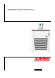
English Operating Manual ME Ultra-Low Refrigerated Circulators F70-ME F81-ME FP89-ME 1.951.0522-V2 19510522-V2.doc 06/13 JULABO GmbH 77960 Seelbach / Germany Tel. +49 (0) 7823 / 51-0 Fax +49 (0) 7823 / 24 91 info@julabo.de www.julabo.de 15.07.
Congratulations! You have made an excellent choice. JULABO thanks you for the trust you have placed in us. This operating manual has been designed to help you gain an understanding of the operation and possible applications of our circulators. For optimal utilization of all functions, we recommend that you thoroughly study this manual prior to beginning operation.
ME TABLE OF CONTENTS Operating manual ............................................................................................................................ 5 1. Intended use ............................................................................................................................. 5 1.1. Description ........................................................................................................................... 5 2. Operator responsibility – Safety recommendations ...
8.2. Switch-over from warning to shutdown function ................................................................ 28 8.3. Over and Sub temperature warning function ..................................................................... 29 9. Menu functions ......................................................................................................... 30 9.1. MENU PROGRAM – START ............................................................................................. 31 9.2.
ME Operating manual 1. Intended use JULABO circulators have been designed to control the temperature of specific fluids in a bath tank. The units feature pump connections for temperature control of external systems (loop circuit). JULABO circulators are not suitable for direct temperature control of foods, semiluxury foods and tobacco, or pharmaceutical and medical products. Direct temperature control means unprotected contact of the object with the bath medium (bath fluid). 1.1.
Operator responsibility – Safety recommendations 2. Operator responsibility – Safety recommendations The products of JULABO ensure safe operation when installed, operated, and maintained according to common safety regulations. This section explains the potential dangers that may arise when operating the circulator and also specifies the most important safety precautions to preclude these dangers as far as possible. The operator is responsible for the qualification of the personnel operating the units.
ME Use: The bath can be filled with flammable materials. Fire hazard! There might be chemical dangers depending on the bath medium used. Observe all warnings for the used materials (bath fluids) and the respective instructions (safety data sheets). Insufficient ventilation may result in the formation of explosive mixtures. Only use the unit in well ventilated areas. Only use recommended materials (bath fluids). Only use non-acid and non corroding materials.
Operator responsibility – Safety recommendations 2.2. EC Conformity The products described in the operating instructions conform to the requirements of the following European guidelines: Directive of the European Parliament and of the Council on the approximation of the laws of the Member States relating to machinery. EMC guideline with respect to legal harmonization of the member countries concerning electromagnetic compatibility. JULABO GmbH Eisenbahnstr. 45 77960 Seelbach / Germany 2.3.
ME 2.4. Technical specifications F70-ME Working temperature range Temperature stability Cooling capacity Medium: ethanol Cooling compressor °C -70 ... 100 °C ±0.02 °C kW +20 0 -20 -40 -60 0.34 0.22 0.17 0.13 0.04 2-stage Refrigerant Overall dimensions R-404A + R-23 (WxDxH) cm 42x54x71 Bath opening (WxL) cm 12x12 Bath depth cm 13 Filling volume liters 3.5 ... 4.
Operator responsibility – Safety recommendations FP89-ME Working temperature range Temperature stability Cooling capacity Medium: ethanol Cooling compressor °C -90 ... 100 °C ±0.02 °C kW +20 0 -20 -40 1.0 0.92 0.88 0.75 2-stage Refrigerant Overall dimensions -60 0.58 -80 0.2 R-404A + R-508b (WxDxH) cm 55x61x90 Bath opening (WxL) cm 13x15 Bath depth cm 16 Filling volume liters 5.5 ...
ME Safety installations according to IEC 61010-2-010: Excess temperature protection adjustable from 0 °C ...
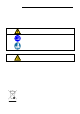
Operating instructions Operating instructions 3. 3.1. Safety notes for the user Explanation of safety notes In addition to the safety warnings listed, warnings are posted throughout the operating manual. These warnings are designated by an exclamation mark inside an equilateral triangle. “Warning of a dangerous situation (Attention! Please follow the documentation).” The danger is classified using a signal word. Read and follow these important instructions for averting dangers.
ME 3.3. Safety recommendations Follow the safety instructions to avoid personal injury and property damage. Also, the valid safety instructions for workplaces must be followed. Only connect the unit to a power socket with an earthing contact (PE – protective earth)! The power supply plug serves as a safe disconnecting device from the line and must always be easily accessible. Place the unit on an even surface on a base made of nonflammable material.
Safety notes for the user Caution: The temperature controlling i.e. of fluids in a reactor constitutes normal circulator practice. We do not know which substances are contained within these vessels. Many substances are: inflammable, easily ignited or explosive hazardous to health environmentally unsafe i.e.: dangerous The user alone is responsible for the handling of these substances! The following questions shall help to recognize possible dangers and to reduce the risks to a minimum.
ME 4. 4.1. Operating controls and functional elements Circulator Front view 1 Rear view Mains power switch, illuminated Navigation keys 2 1. Key: >OK< Start / Stop (pump / heater ) 2. >OK< in the menu Menu item / select submenu for setting Save set value Save selected parameter A beep signals the end of setting After the actions Start, Stop and change from VFD Display to standard display the key is locked for a short time. The above graph “front side” shows an example for standard display. 3 1.
Operating controls and functional elements Menu keys 5 Key: start the menu > warning and safety values< 6 Key: start the menu >temperature setpoints< 7 Key: display of MENU structure 10 VFD COMFORT-DISPLAY Header: Control indicators see sections 11 and 12 Line 1: Actual value internal or external The display is depending on the selected control mode in the menu > Control < (internal or external). Line 2: Working temp. setpoint, constantly S xxx.
ME 4.2.
Preparations 5. 5.1. Preparations Installation Place the unit on an even surface on a base made of nonflammable material. The place of installation should be large enough and provide sufficient air ventilation to ensure the room does not warm up excessively because of the heat the instrument rejects to the environment. (Max. permissible ambient temperature: 40 °C).
ME Recommended bath fluids: Bath fluid soft/decalcified water mixture water/glycol, mixture 1:1 Temperature range 5 °C to 80 °C -20°C to 50°C JULABO bath fluids JULABO Description Order Number 10 liters 5 liters °C °C °C Temperature range Flash point Fire point Color JULABO Description Order Number 10 liters 5 liters °C °C °C Temperature range Flash point Fire point Color Thermal G 8 940 124 8 940 125 -30 ... 80 --light yellow Thermal HY 8 940 104 8 940 105 -80 ...
Preparations 5.3. Temperature application to external systems Caution: Securely attach all tubing to prevent slipping. If the circulator is operated without external system, close the pump connector (24a) with the cap nut. The circulator is used for temperature application to external, closed systems (loop circuit) with simultaneous temperature application in the circulator bath. Connecting the external system Unscrew the collar nuts from the pump connector (24a).
ME Safety recommendations Employ suitable connecting tubing. Make sure that the tubing is securely attached. Avoid sharp bends in the tubing, and maintain a sufficient distance from surrounding walls. Regularly check the tubing for material defects (e.g. for cracks). Preventive maintenance: Replace the tubing from time to time. 5.4. Filling/draining Notice Pay attention to the thermal expansion of bath oil during heating to avoid overflowing of the liquid.
Operating procedures Entry of ice flakes/water into the bath oil At working temperatures below 0 °C, humidity from the atmosphere may enter the bath oil through condensation. This may subsequently result in the formation of ice flakes, impairing the operation of the pump. For this reason, the bottom of the bath tank provides a groove sloping down towards the drain tap. Thus, water having entered the bath oil gathers in the groove immediately behind the drain tap.
ME 6.2. 6.2.1. Switching on / Start - Stop Switching on the circulator Switching on: Turn on the mains power switch (1). The unit performs a self-test. Then the software version (example: V 1.xx) appears. The display „OFF“ or „R OFF“ indicates the unit is ready to operate. The circulator enters the operating mode activated before switching the circulator off: keypad control mode (manual operation) or remote control mode (operation via personal computer). Start: key.
Setting of temperatures Control of the FP89 cooling machine: The mains switch is turned on. After pressing the start/stop button, the cooling machine is automatically switched on or off by the circulator. In the start mode of the circulator, the cooling machine runs continuously. Immediately after starting the cooling machine, the output of the system is reduced to a minimum value for a defined period in order to equilibrate the cooling system.
ME Example: Adjustment/modification of the pre-setting of "SETPOINT 3" 1. Press the key. 2. Select SETPOINT 3 by pressing the Example: SETPNT 3 / 70.00 °C 3. Keep the (example: <70>) key. key pressed until the integer digits flash 4. Adjust value by pressing the key and the . key to 85.00 °C key. and confirm by pressing the The decimal digits flash and can be adjusted if desired. Confirm once more by pressing the Example on the left: SETPNT 3 / 85.00. key.
Safety installations, warning functions 8. Safety installations, warning functions Check the safety installations at least twice a year! Refer to ( page 14) SECVAL (Security Values) SAFETMP AL-TYPE OVERTMP SUBTEMP 8.1. Settings for the excess temperature protection > SAFETMP< and for the warning functions for high > OVERTMP< and low > SUBTEMP< temperature are made in a menu which is called up by .
ME 8.1.1. Early warning system, low level protection This low level protection is independent of the control circuit and is divided into two sections: . 1. Switch in stage 1 recognizes a defined fluid level An audible warning sounds (interval tone) and together with the ticker: > LOW LEVEL WARNING-FILL MEDIUM < a message appears on the VFD COMFORT-DISPLAY: Refill the bath fluid! . 2.
Safety installations, warning functions 8.2. Switch-over from warning to shutdown function If a shutdown of functional elements (e.g. heater, circulating pump) is required when the limit values are exceeded or undercut the circulator can be changed over from warning function >WARNING< to shutdown function >ALARM<. Factory setting: >WARNING< 1. Press the key . 2. Select the menu >SECVAL -AL-TYPE< by pressing the 3. Press the key and the set parameter will flash (Example: WARNING) 4.
ME 8.3. Over and Sub temperature warning function Over temperature If the observance of a working temperature value >SETP< has to be supervised for a sensitive temperature application, then set over and sub temperature warning values. In the example below the SETPOINT 85 °C is surrounded by the values OVERTMP 87 °C and SUBTEMP 83 °C. The electronics immediately register if the actual temperature breaches one of the set limit values. The resulting reaction is defined in a further menu item.
Menu functions 9.
ME 9.1. MENU PROGRAM – START This menu will start a previously set program. Requirements: 1. Create a program. (refer to next chapter) 2. Return to the Start-MENU and confirm the desired setting of each Start-Menu MENU item with the key 3. Set a start time (>TIME< >DATE< >YEAR<) if the program is to be started by the internal timer. Menu level 1 > STEP< Program start at section 1 … 10 > RUNS < > END< Number of repetitions 1 ...
Menu functions Submenu TIMER set the time for the start of the program in the submenu >TIMER<. Parameter level >TIME< hours/minutes (hh:mm), set both values one after the other and confirm hours flash, set by pressing + minutes flash, set by pressing + >DATE< day/months (TT/MM), set both values one after the other and confirm. day flashes, set by pressing + month flashes, set by pressing + >YEAR< year Set the year with and . The program starts at the set time.
ME D C2 D1 E xxx.xx – external actual value RUN – the program has started or PAUSE – the progress of the program has been interrupted by pressing the key. While the time is stopped the temperature will constantly remain at the last calculated setpoint Continue with the key. D2 Termination / Interruption of a program The program can be terminated any time by pressing the key In case of power failure the program is interrupted. . The circulator switches to –OFF- .
Menu functions >EDIT< Menu level 1 > DELETE< Create, administer program > STEP< Program step (1 ... 10) >SETPNT < Temperature setpoint of step ... >TSLICE< Duration of step ... delete program step (01 … 10, ALL) Level 2 Press key, if a parameter is to be retained.
ME 9.3. MENU PUMP – Setting of pump pressure The capacity of the circulating pump is set by adjusting the motor speed Settings: stage / LEVEL 1 ... 4 Display: with illuminated indicator Flow rate: Pump pressure: Factory setting: stage 2 1. Press the 11 ... 16 l/m 0,22 ... 0,45 bar key. key and confirm by 2. Select the menu >PUMP< pressing the pressing the key The set parameter flashes (example: >LEVEL 2<) 3. Change the parameter by pressing and confirm by pressing the key.
Menu functions 9.4. MENU CONFIG – Configuration of unit Menu level 1 A RESET can be effected only in the >OFF< mode. Switch off circulator by pressing the key and call up the menu CONFIGURATION. Level 2 Parameter level Press the key if a parameter is to be retained. Correction function for parameters and values (prior to OK). Switch on and off remote control by pressing and or Control display in the topline for Remote For remote control refer to 57 Connect RS232 with PC.
ME Level 3 Parameter level Year flashes, set by pressing Return to factory settings by pressing RESET returns all set values to the factory setting except for date and time. 9.4.1. + A RESET can be effected only in the –OFF- mode. During the messate –RUN- all parameters are reset to factory settings. REMOTE Factory setting: OFF The control electronics offer two ways of adjusting a setpoint. 1. Adjustment of setpoint using the keypad or the integrated programmer. 2.
Menu functions interface. If such a safety standard is not required, the NAMUR recommendations can be bypassed with the AUTOSTART function thus allowing a direct start of the circulator by pressing the mains switch or using a timer. 9.4.3. OFF-MODE Factory setting: PMP OFF Usually the circulating pump is controlled with the key or the start/stop command. If the circulating pump is to work in the –OFFmode, the adjustment can be set in a sub-menu.
ME 9.5. MENU CONTROL – Control characteristics and parameters The circulator is qualified for internal and external temperature control The switchover is carried out in the menu >C-TYPE< .(INT or EXT). Menu level 1 Level 2 For external temperature control and measurement connect a Pt100 external sensor to the socket at the rear of the circulator. Press the key if a parameter is to be retained.
Menu functions Level 2 Parameter level The parameter flashes, set by pressing + 0 … 999 The parameter flashes, set by pressing + 0.1 … 99.9 9.5.1. CONTROL – Control INTERNAL / EXTERNAL Pt100 Switchover can only be effected if a Pt100 external sensor is connected. Factory setting: INT IMPORTANT: Additional measures for external temperature control Suggested settings for external temperature control: BAND HIGH / LOW and INTERN MAX / MIN see chapter >LIMITS< page 50.
ME 9.5.2. Dynamic internal This parameter affects the temperature sequence only in case of internal control. °C Factory setting: NORM temp. stability Possible parameters: APER NORM Allows for reaching the setpoint faster – with setpoint change or ramp function – but overshooting of up to 5 % is possible. APER Ramp function: the increase of temperature occurs temporally offset and achieves the target temperature without overshooting.
Menu functions 9.5.4. Control parameters– XP-, TN-, TV- INTERNAL In most cases the control parameters preset in the factory are adequate for achieving an optimum temperature sequence. The control parameters allow adjustment to special control processes.. Proportional range >Xp< Setting range: 0.1 ... 99.9 The proportional range is the range below the setpoint in which the control circuit reduces the heating capacity from 100% to 0 % Reset time >Tn< (Integral component) Setting range: 3 ...
ME 9.6. MENU SERIAL - BAUDRATE, HANDSHAKE, PARITY For communication between circulator and a PC or a superordinated process control system the interface parameters of both units must be identical. Menu level 1 For remote control refer to page 57 Factory settings: 4800 Baud even hardware handshake Level 2 Parameter level Press the retained.
Menu functions 9.7. MENU ATC - Absolut Temperature Calibration ATC serves to compensate a temperature difference that might occur between circulator and a defined measuring point in the bath tank because of physical properties. Principle: For ATC calibration, in steady state the bath temperature at the location of the temperature sensor (CT) is determined at the respective adjusted working temperature. This value is then set on the circulator in the menu >ATCalibration< under menu item > CTEMP X <.
ME Menu level 1 Level 2 Parameter level or Press the key if parameter is to be retained. Correction function for parameters or values (prior to OK). The parameter flashes, switch by pressing and On level 2 a (I) is indicated for internal or an (E) for external. Example: or The parameter flashes, switch by pressing and >NO< Carry out an ATC calibration >YES< return to standard operation after calibration.
Menu functions The value is only indicated Integer digits flash, set by pressing + Decimal digits flash, set by pressing + If only a 2-point calibration is carried out, the following menu items are not indicated anymore The value is only indicated Integer digits flash, set by pressing + Decimal digits flash, set by pressing + 9.7.1. ATC SENSOR - INTERNAL / EXTERNAL In the first submenu the ATC function is set for the >INTERN< internal or the >EXTERN< external temperature sensor.
ME 9.7.3. CALIBRATION TYPE: 1 -/ 2 -/ 3 POINT A >1-point<, >2-point< or >3-point< calibration can be carried out. First geometrically define the location for calibration (measuring point CT), then determine the temperature values of the calibration points. The type of calibrations also determines the number of the following pairs of values indicated on the LCD DIALOG-DISPLAY.
Menu functions 9.7.4. Example: 3-point calibration for internal control In the temperature range from 80 °C to 160 °C the calibration curve of the temperature sensor (TT) is to be adjusted to the actual temperatures at measuring point (CT). 1. Set circulator to internal control: MENU CONTROL page 39 Menu level 1 The type of control can be set only in the –OFF- mode. 2.
ME An ATC calibration is to be carried out. Set to >NO< The parameter flashes, switch by pressing and . The parameter flashes, switch by pressing and . A >3-point< calibration is carried out. The value >TMPVAL< is only indicated In addition the measured value >CALVAL X< is saved during the following step Integer digits flash, set by pressing (79) + Decimal digits flash, set by pressing (70) + The first of 3 points is calibrated. Return to 2. Set working temperature value SETPNT: 120.
Menu functions 9.8. MENU LIMITS Menu level 1 Level 2 Parameter level key if parameter is to be retained. Press the Correction function for parameters or values (prior to OK).
ME 9.8.1. Limits for internal control SETPOINT MAX / MIN – Maximum and minimum setpoint Restriction of the adjustable temperature range The limitation of the operating temperature range effects the temperature setting in the menu with the key . Only setting of working temperatures which lie within the determined limits is possible Existing settings for SETPNT 1, -2, -3, as well as those for >OVERTMP< and > SUBTMP < (refer to page 29), are automatically deferred into the limit range.
Menu functions BAND HIGH / LOW – Band limitation The band limitation is active during external control. Varied, practiceoriented setting are feasible for heat-up and cool-down phases. Setting range: 0 °C ... 200 °C BAND HIGH and BAND LOW allow for the limitation of the difference between the temperatures in the internal bath and the external system to any maximum value for the heat-up and cool-down phase. During the heat-up phase this difference value is always added to the actual external temperature.
ME 10. Troubleshooting guide / error messages Alarm with complete shutdown: If one of the following failures occur a complete, all-pole shutdown of the heater and circulating pump is effected. + „ “ lights up and a continuous signal sounds. The code for the cause of alarm is indicated on the VFD COMFORTDISPLAY. Alarm without shutdown: The code for the cause of alarm is indicated on the VFD COMFORTDISPLAY. The warning signal sounds in regular intervals. The messages appear every 10 seconds.
Troubleshooting guide / error messages Error message with ticker: >SENSOR DIFFERENCE ALARM-CHECK VISCOSITY AND PUMP STAGE< Defect of working or excess temperature protector. Working temperature sensor and excess temperature protector report a temperature difference of more than 35 K. Error message with ticker: > INTERNAL HARDWARE ERROR-CALL SERVICE < Other errors Error in A/D converter Error message with ticker: > EXCESS TEMPERATURE PROTECTOR ALARM-CHECK ADJUSTMENT < Excess temperature protector defect.
ME Short circuit of control line to cooling machine during self-test. Error message with ticker: > SAFETY SENSOR ALARM-CALL SERVICE < The cable of the excess temperature protector has been disconnected or short-circuited Error message with ticker: > LOW LEVEL WARNING-FILL MEDIUM < The early warning system for low level reports a critical fluid level. Refill bath fluid. By quickly switching off and restarting the unit the alarm is cancelled.
Electrical connections 11. Electrical connections Notice: Use shielded cables only. The shield of the connecting cable is electrically connected to the plug housing. The unit ensures safe operation if connecting cables with a maximum length of 3 m are used. The use of longer cables does not affect proper performance of the unit, however external interferences may have a negative impact on safe operation (e.g. cellular phones).
ME / Control output 4 2 1 12. The connector may be used for control of JULABO refrigerated circulators or as output for alarm messages. Circuit: Operation = relay powered Alarm = relay not powered 5 Pin assignment: Pin Signal 1 +24 V (I max. current 25 mA) 2 0V 3 Alarm relay 4 Reserved - do not use! 5 Cooling pulse 3 Remote control 12.1. Setup for remote control 5 9 1 6 RS232C 1. Check the interface parameters for both interfaces (on circulator and PC) and make sure they match.
Remote control 12.2. Communication with a PC or a superordinated data system If the circulator is put into remote control mode via the configuration level, the VFD COMFORT-DISPLAY will read “R -OFF-” = REMOTE STOP. The circulator is now operated via the computer. In general, the computer (master) sends commands to the circulator (slave). The circulator sends data (including error messages) only when the computer sends a query.
ME 12.3. List of commands out commands: Setting temperature values or parameters. Command Parameter Response of circulator out_mode_01 0 Use working temperature > SETPNT 1< out_mode_01 1 Use working temperature > SETPNT 2< out_mode_01 2 Use working temperature > SETPNT 3< out_mode_04 0 Temperature control of internal bath. out_mode_04 1 External control with Pt100 sensor. out_mode_05 0 Stop the unit = R –OFF-. out_mode_05 1 Start the unit.
Remote control in commands: Asking for parameters or temperature values to be displayed. Command Parameter Response of circulator version none Number of software version (V X.xx) status none Status message, error message (see page 61) in_pv_00 none Actual bath temperature. in_pv_01 none Heating power being used (%). in_pv_02 none Temperature value registered by the external Pt100 sensor. in_pv_03 none Temperature value registered by the safety sensor.
ME Command Parameter Response of circulator in_mode_01 none Selected setpoint: 0 = SETPNT 1 1 = SETPNT 2 2 = SETPNT 3 3 = Last setpoint setting was carried out through an external programmer in_mode_04 none Internal/external temperature control: 0 = Temperature control with internal sensor. 1 = Temperature control with external Pt100 sensor. in_mode_05 none Circulator in Stop/Start condition: 0 = Stop 1 = Start in_mode_08 none Adjusted control dynamics 0 = aperiodic 1 = standard 12.4.
Remote control Error messages Description -06 SENSOR DIFFERENCE ALARM Sensor difference alarm. Working temperature and safety sensors report a temperature difference of more than 35 K. -07 I2C-BUS ERROR Internal error when reading or writing the I2C bus. -08 INVALID COMMAND Invalid command. -09 COMMAND NOT ALLOWED IN CURRENT OPERATING MODE Invalid command in current operating mode. -10 VALUE TOO SMALL Entered value too small. -11 VALUE TOO LARGE Entered value too large.
ME 13. JULABO Service – Online remote diagnosis JULABO circulators of the HighTech series are equipped with a black box. This box is implemented in the controller and records all significant data for the last 30 minutes. In case of a failure, this data can be read out from the unit by using special software. This software is available as a free download from www.julabo.de \ EasyBlackBox. Installation is easy and is performed step by step. Please observe the instructions.
Cleaning / repairing the unit 14. Cleaning / repairing the unit Caution: Always turn off the unit and disconnect the mains cable from the power source before cleaning the unit. Prevent humidity from entering into the circulator. Electrical connections and any other work must be performed by qualified personnel only. Maintaining the cooling performance In dusty environments, the cooling machine’s condenser should be cleaned by vacuuming every 1 to 2 months.