
User Manual
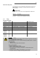

HE
23
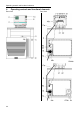
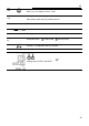
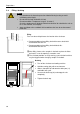
1a
1b
Mains power switch, illuminated for circulator
Mains power switch, illuminated for cooling machine
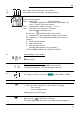
2
VFD COMFORT-DISPLAY
Header: Control indicators
Line 1: Actual value internal or external
The display is depending on the selected control mode in the
menu > Control < (internal or external).
Line 2: Working temp. setpoint, constantly S xxx.xx
Line 3: Actual value (E = external or I = internal)
Alternating with the display in line 1
Use the keys
to indicate further values in line 3
PI Capacity in % - with manipulated variable set to >control<*
PS Capacity in % - with manipulated variable set to >serial<* or
>eprog<*
H Heater capacity in Watts
U Mains voltage Volts
F Flow rate in liters/minute
(providing EPROG input set to >Flowrate<)
*refer to >MENU/CONFIG<
>CONFIG / ACTVAR>
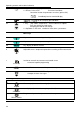
2.1
Control indicators in the header:
Heating / Cooling / Alarm /
Remote control
2.2
Control indicators in the header:
Temperature indication Internal or External actual value
Temperature indication in °C (°F not possible on this unit)
2.3
Display of set pump pressure stage
Four stages, can be set via the key
, under >MENU - PUMP<.
4
Navigation keys
4.1
1. Key: >OK< Start / Stop (pump / heater )
2. >OK< in the menu Menu item / select submenu for setting
Save set value
Save selected parameter
A beep signals the end of setting
After the actions Start, Stop and change from VFD Display to standard
display the key
is locked for a short time.
The above graph “front side” shows an example for standard display.