English Operating Manual Calibration Baths SL-8K SL-14K 1.951.2826-V2 19512826-V2.doc 06/13 JULABO GmbH 77960 Seelbach / Germany Tel. +49 (0) 7823 / 51-0 Fax +49 (0) 7823 / 24 91 info@julabo.de www.julabo.de 22.07.
Congratulations! You have made an excellent choice. JULABO thanks you for the trust you have placed in us. This operating manual has been designed to help you gain an understanding of the operation and possible applications of our circulators. For optimal utilization of all functions, we recommend that you thoroughly study this manual prior to beginning operation.
SL TABLE OF CONTENTS Operating manual .................................................................................................................. 5 1. Intended use ................................................................................................................... 5 1.1. Description ................................................................................................................. 5 2. Operator responsibility – Safety recommendations ......................................
9.4.5. ActVar - actuating variable ................................................................................... 46 9.4.6. Setting of clock and date ...................................................................................... 47 9.4.7. Language ............................................................................................................. 47 9.4.8. Unit ....................................................................................................................... 47 9.
SL Operating manual 1. Intended use JULABO circulators have been designed to control the temperature of specific fluids in a bath tank. JULABO circulators are not suitable for direct temperature control of foods, semiluxury foods and tobacco, or pharmaceutical and medical products. Direct temperature control means unprotected contact of the object with the bath medium (bath fluid). 1.1. Description ICC TCF ATC3 The circulators are operated via the splash-proof keypad.
Operator responsibility – Safety recommendations 2. Operator responsibility – Safety recommendations The products of JULABO ensure safe operation when installed, operated, and maintained according to common safety regulations. This section explains the potential dangers that may arise when operating the circulator and also specifies the most important safety precautions to preclude these dangers as far as possible. The operator is responsible for the qualification of the personnel operating the units.
SL Use: The bath can be filled with flammable materials. Fire hazard! There might be chemical dangers depending on the bath medium used. Observe all warnings for the used materials (bath fluids) and the respective instructions (safety data sheets). Insufficient ventilation may result in the formation of explosive mixtures. Only use the unit in well ventilated areas. Only use recommended materials (bath fluids). Only use non-acid and non corroding materials.
Operator responsibility – Safety recommendations 2.2. EC Conformity The products described in the operating instructions conform to the requirements of the following European guidelines: Directive of the European Parliament and of the Council on the approximation of the laws of the Member States relating to machinery. EMC guideline with respect to legal harmonization of the member countries concerning electromagnetic compatibility. JULABO GmbH Eisenbahnstr. 45 77960 Seelbach / Germany 2.3.
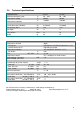
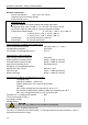
SL 2.4. Technical specifications Calibration Baths °C °C SL-8K 50 ... 300 ±0.005 SL-14K 50 ... 300 ±0.005 °C <±0.008 <±0.008 Overall dimensions (WxDxH) Bath opening (WxL) cm cm 21x42x46 21x42x60 Bath depth Filling volume Weight cm Liter kg 12 17 14 48 12 31 24 51 Working temperature range (1 Temperature stability Temperature uniformity kW SL C digital indication on LCD DIALOG-DISPLAY (°C/°F) indication on monitor VFD COMFORT-DISPLAY (°C/°F) 0.
Operator responsibility – Safety recommendations Electrical connections: External alarm device 24-0 V DC / max. 25 mA Computer interface RS232 or RS485 External Pt100 sensor Optional for HL, SL (Order No.
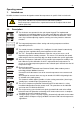
SL Operating instructions 3. 3.1. Safety notes for the user Explanation of safety notes In addition to the safety warnings listed, warnings are posted throughout the operating manual. These warnings are designated by an exclamation mark inside an equilateral triangle. “Warning of a dangerous situation (Attention! Please follow the documentation).” The danger is classified using a signal word. Read and follow these important instructions for averting dangers.
Safety notes for the user 3.3. Safety recommendations Follow the safety instructions to avoid personal injury and property damage. Also, the valid safety instructions for workplaces must be followed. Only connect the unit to a power socket with an earthing contact (PE – protective earth)! The power supply plug serves as a safe disconnecting device from the line and must always be easily accessible.
SL Caution: The temperature controlling i.e. of fluids in a reactor constitutes normal circulator practice. We do not know which substances are contained within these vessels. Many substances are: inflammable, easily ignited or explosive hazardous to health environmentally unsafe i.e.: dangerous The user alone is responsible for the handling of these substances! The following questions shall help to recognize possible dangers and to reduce the risks to a minimum.
Operating controls and functional elements 4. Operating controls and functional elements Front view Rear view 1 Mains power switch, illuminated 2 VFD COMFORT-DISPLAY Header: Control indicators Line 1: Actual value internal or external The display is depending on the selected control mode in the menu > Control < (internal or external). or Actual value of the precision reference sensor „C“ xxx.xx Line 2: Working temp. setpoint, constantly S xxx.
SL 2.1 Control indicators in the header: Heating / Cooling / Alarm / Remote control 2.2 Control indicators in the header: Temperature indication Internal or External actual value Temperature indication in °C or °F 2.3 Display for the adjusted pump pressure stage in the -OFF- mode. Display for the effective pump pressure stage (rotation speed) after start. button, in the menu >PUMP<.
Operating controls and functional elements 4.2 1. Key: >Return< Stop (pump / heater) Special display on VFD Display leave line 3. 2. >Return< in the menu one menu level down Correction function for parameters or values (prior to OK) immediately back to standard display - icon for „keep key pressed down“. 1. Key: >Up / Down Up/Down< in the menu selection of menu items / parameters 4.
SL Option: Electronic module Order No. 8 900 100 The circulator automatically recognizes the connected electronic module.
Preparations 5. 5.1. Preparations Installation Place the unit on an even surface on a pad made of non-flammable material. Pump motor and electronics produce intrinsic heat that is dissipated via the venting openings! Never cover these openings! Do not set up the unit in the immediate vicinity of heat sources and do not expose to sun light The bath cover (1) is mounted on the bath tank with 4 captive screws (2).
SL Recommended bath fluids: Bath fluid Temperature range soft/decalcified water 5 °C to 80 °C JULABO bath fluids JULABO Description Order Number 10 liters 5 liters °C °C °C Temperature range Flash point Fire point Color JULABO Description Order Number 10 liters 5 liters °C °C °C Temperature range Flash point Fire point Color Thermal G 8 940 124 8 940 125 -30 ... 80 --light yellow Thermal M 8 940 100 8 940 101 40 ... 170 284 306 clear Thermal H10 8 940 114 8 940 115 -20 ...
Preparations 5.3. Filling / draining Notice: Pay attention to the thermal expansion of bath oil during heating to avoid overflowing of the liquid. Do not drain the bath fluid while it is hot! Recommendation: Temperature range 5 °C to 40 °C Check the temperature of the bath fluid prior to draining (by switching the unit on for a short moment, for example). Store and dispose the used bath fluid according to the laws for environmental protection.
SL 5.4. Counter-cooling Caution: Securely attach all tubing to prevent slipping. Observe the laws and regulations of the water distribution company valid in the location where the unit is operated. ext Pt100 T16A SERIAL ALARM STAND-BY REG+ E-PROG For applications near the ambient temperature, the cooling coil (20) must be connected to the water mains. Using tubing, connect the cooling coil to the tap water supply, and lead the tap water in a sink through the return connector.
Operating procedures 6. 6.1. Operating procedures Power connection Caution: Only connect the unit to a power socket with earthing contact (PE – protective earth)! The power supply plug serves as safe disconnecting device from the line and must be always easily accessible. Never operate equipment with damaged mains power cables. Regularly check the mains power cables for material defects (e.g. for cracks).
SL 6.3. Start - Stop Start: key. Press The actual bath temperature is displayed on the VFD COMFORTDISPLAY. The circulating pump starts with a slight delay. Stop: Press or Keep key. key pressed. The VFD COMFORT-DISPLAY indicates the message "OFF". 6.4. Adjusting the temperature chamber Adjusting the temperature chamber after set up: If bath fluid overflow in the temperature chamber is not equal in every direction, an adjustment can be made with the 3 screws that are accessible from above.
Setting of temperatures 7. Setting of temperatures Press the key to call up the menu for temperature selection. 3 different working temperatures can be adjusted. Their values are freely selectable within the operating temperature range. The temperatures can be set in start or stop mode. menu Setting of working temperature in the Factory settings: 1. Press the key . The value flashes 2. Select SETPOINT 1 or 2 or 3 using the key 3. Confirm by pressing the or . key.
SL Warning: The excess temperature protection must be set at least 25 °C below the fire point of the bath fluid used! In case of wrong setting there is a fire hazard! We disclaim all liability for damage caused by wrong settings! SafeTemp: Setting range: 20 °C ... 320 °C Rough setting can be effected by using the temperature scale. Settings: SafeTemp: Type: Press the key and by pressing the key or and confirm the by pressing the key . menu item select the For setting proceed as follows.
Safety installations, warning functions complete shutdown of the heater and pump is effected. The alarm is indicated by optical and audible signals (continuous tone). The following error message appears on the VFD COMFORT-DISPLAY: for help on the LCD Press Depending on the setting of >ControlType - internal or external< the actual temperature values for both sensors are shown/indicated on both displays. Examples: I 94.06 and Ext. : xx.
SL Setting >WARNING< A mere warning function with optical and audible warning signal (interval tone) A message appears on the VFD COMFORT-DISPLAY: or OverTemp SubTemp The LCD –DISPLAY shows the message: Setting >ALARM< Temperature limit with shutdown of heater and circulating pump.
Safety installations, warning functions 8.0.1. Early warning system, low level protection This low level protection is independent of the control circuit and is divided into two sections: DBGM: 20306059.8 1. Switch in stage 1 recognizes a critical fluid level . An audible warning (interval tone) sounds and a message appears on the VFD COMFORT-DISPLAY. Refill bath fluid! 2. Switch in stage 2 recognizes a low fluid level .
SL 9. Menu functions The term „menu functions“ refers to adjustments such as Menu level 1 Start program Page 31 This menu will start a previously set program. Administration and creation of programs Page 36 Electronically adjustable pump capacity Page 40 The capacity of the circulating pump is set by adjusting the motor speed.
Menu functions Menu level 1 Adjustable interface parameters BAUDRATE, PARITY, HANDSHAKE Page 55 ATC - Absolute Temperature Calibration, Sensor calibration internal sensor, Sensor calibration external sensor 3-point calibration Page 56 Limitations of temperature and capacity Page 63 Setpoint Max / Min - Maximum and minimum setpoint Heating Max – Set maximum heating Cooling Max – Set maximum cooling Internal Max / Min – Limitation of the temperature range Upper band / Lower band – Band limit Analog inputs
SL 9.1. Start of a program The start menu of the integrated programmer allows one of six previously stored temperature programs to be called up and started. The profiles are started manually or via the integrated timer. Requirements: 1. Create a program. (refer to next chapter) 2. Return to the Start-MENU and confirm the desired setting of each MENU item with the key 3. Set a start time (>TIME< >DATE< >YEAR<) if the program is to be started by the internal timer.
Menu functions Level 2 Parameter /Value or Set desired parameters with and . Confirm >now< with the key and the program will start immediately or start at the set time under parameter (time ). Set time in the example below: 09. August 2009, 11:15 hrs Submenu TIMER If the parameter time is selected, a further submenu opens for setting the start time. Set the time for the start of the program in the submenu >3 TIMER<.
SL 9.1.1. Status at the end of a program Program end StdBy , PSetp, Setp 1, Setp 2 , Setp 3 This parameter is used to determine if the unit switches to the -OFFcondition at the end of a profile or if temperature control is continued, and the working temperature setpoint that is to be used if temperature control is continued. StdBy – If the end of the profile is reached, the circulator switches to the -OFF- condition.
Menu functions 9.1.3. Editing after Start The programmer allows a running program to be edited. Initiation and exit of the editing function: After the start enter the submenu „3 EDITOR“.by pressing the key See chapter „program administration, creation“ page 36 Exit the editing modus anytime by pressing the key . Particularity for changes in a section that is currently in process.
SL 9.1.5. Interruption after a power failure It is possible to operate the programmer safely in case of a power failure. Important: For this, >Autostart< needs to be set in the >Configuration< menu. If the AUTOSTART function is activated, the programmer starts again at a point approx. 20 seconds before the interruption took place. However, an uncontrolled change of the bath temperature has occurred.
Menu functions 9.2. Program administration, creation The integrated programmer permits fast and easy programming of setpoint temperature sequences. This temperature sequence is called program. A program is composed of individual sections (Step). The sections are defined by duration (t) or Gradient (°/t) and target temperature. The target temperature is the setpoint (SP), which is achieved at the end of a section. The programmer calculates the temperature ramp from the difference in time and temperature.
SL Editing PrgNr: Set the program you wish to create. 0 ... 5 SP: Setpoint TI : GRD: Time [hh:mm] or Gradient [°/t] = [°/min] Change type of program in MENU >configuration<, menu item >Programmtyp/program type< . ST: Step Press the 0 … 59 key if a parameter is to be retained. (prior to OK) Level 2 Example: Program (PrgNr.) 2 is to have a target temperature with a set point (SW) of 100.00 °C in section t (ABS) 3. Duration (ZI) 1 hour. Select the program number. Set the desired >PrgNr.
Menu functions Delete It is possible to delete an entire program or consecutive sections Delete PrgNr: Set the program you wish to delete 0 ... 5 Delete from Step X to Step X (0 … 59) Press the key if a parameter is to be retained. (prior to OK) Level 2 Submenu >Delete< Set menu item >Delete PrgNr.< by pressing and . Set desired PrgNr with and . Example: PrgNr. 0 Level 3 38 Input window: delete sections. Select menu items > from Step< and > to Step< one and .
SL Print Every program can be printed via the serial interface for control and documentation purposes. Press the key if a parameter is to be retained. (prior to OK) Level 2 Submenu >Print< Set menu item >Print PrgNr.< by pressing and . Set desired >PrgNr.< by pressing and . Example: 4 Level 3 Confirm Confirm >Print?< by pressing Printing and end of printing are confirmed by successive messages on the LCD display as shown on the left. > Print< by pressing . .
Menu functions 9.3. Setting the pump pressure The capacity of the circulating pump is set by adjusting the motor speed Press the key if a parameter is to be retained. (prior to OK) Submenu >Pump< Level 2 The set pump stage is displayed. Example: 1 Confirm by pressing Set required pump stage by pressing and . . Example: 3 Example: Adjusted Adjustable pump capacity Effective Illuminated display: stage 1 ...
SL 9.4. Configuration Level 2 Press the key if a parameter is to be retained. (prior to OK) Parameter level Remote control via serial interface. Possible parameters: off / on or Switch on and off remote control by and pressing First set the >type< of interface (RS232 or RS485) in the MENU >INTERFACE SERIAL< and then switch >Remote< to >on<. Control display in the top line for Remote Connect SERIAL with PC.
Menu functions Level 2 Parameter level Pump-Mode Possible parameters: P. on / P. off Switch on and off >Off-Mode by pressing and P.on continuous operation of circulating pump P.off circulating pump is linked to Start/Stop ActVar - actuating variable Possible parameters: control, Eprog, serial Set desired parameters with and .
SL Level 2 Parameter level Reset Return to factory settings by pressing >Reset?< returns all set values to the factory setting except for date and time. A RESET can be effected only in the – OFF- mode. During the message >Running < all parameters are reset to factory settings. C-Sensor (Precision Pt100 reference sensor) Possible parameters: yes / no Level 2 Level 3 Set desired parameters with and .
Menu functions 9.4.1. Remote control via the serial interface Factory setting: off Setpoint is set via the serial RS232/RS485 interface through a PC or superordinated data system. In the header of the VFD COMFORT-DISPLAY, an “R” illuminates. It indicates that remote control mode is active. The selected setting is shown on the LCD DIALOG-DISPLAY.
SL 9.4.3. Autostart Possible parameters: on - Autostart on off - Autostart off (Factory setting) Note: The circulator has been configured and delivered by JULABO according to N.A.M.U.R. recommendations. This means for the start mode that the unit must enter a safe operating state after a power failure (nonautomatic start mode). This safe operating state is indicated by “OFF” or “R OFF” on the VFD-COMFORT-DISPLAY.
Menu functions 9.4.5. ActVar - actuating variable The variable (ACTuating VARiable) corresponds to the extent to which the heater or cooling unit of the circulator is controlled. Heat or cold is applied to the bath according to this variable. If this happens with the control electronics of the circulator, called > control < in this particular case, the bath temperature is exactly heated and maintained constant at the adjusted setpoint.
SL 9.4.6. Setting of clock and date The internal real time clock allows starting a program any time. The clock is set to the local mean time (MEZ) at the factory. 9.4.7. If the unit is operated in a different time zone, the clock can be adjusted in this menu. Change summer/winter time in this menu Language There are two options for the language of the LCD DIALOG-DISPLAY: German and English. Possible parameters: deutsch / english 9.4.8. Unit Temperature values can be displayed in °C or °F.
Menu functions 9.4.11. C-Sensor - Precision reference sensor Temperature measurement with a precision reference sensor Factory setting: no 5 1 9 6 Precision reference sensor for applications in quality assurance, calibration services and laboratories. Possible parameters: SERIAL yes – Temperature measurement with a precision reference sensor no Connect the higly accurate temperature sensor to the RS232 socket (SERIAL) on the rear of the circulator.
SL 9.5. Control The circulator is designed for internal and external temperature control. This can be switched in this submenu. Only the set of parameters corresponding to the particular setting is displayed. Control internal Control external For external temperature control and measurement connect a Pt100 external sensor to the socket at the rear of the circulator. Press the key if a parameter is to be retained.
Menu functions Control Type internal Parameter-Level The value flashes. Set by using the numeric keypad and confirm by pressing . Example: Setting range: 0.1 … 99.9 K The value flashes. Set by using the numeric keypad and confirm by pressing . Setting range: 3 … 9999 s The value flashes. Set by using the numeric . keypad and confirm by pressing Setting range: 0 … 999 s Control Type external Parameter-Level The value flashes. Set by using the numeric keypad and confirm by pressing .
SL 9.5.1. Control internal / external The control type can be adjusted in the -OFF- mode only. Possible parameters: intern internal temperature control extern external temperature control with external Pt100 sensor IMPORTANT: Additional measures for external temperature control. ext. Pt100 Connect a Pt100 sensor to the socket on the rear of the circulator. Sensor calibration of the external Pt100 sensor is performed in the >ATCalibration< menu.
Menu functions 9.5.2. Selftuning When performing a selftuning for the controlled system (temperature application system), the control parameters Xp, Tn and Tv are automatically determined and stored. Possible parameters: off - no selftuning The control parameters ascertained during the last identification are used for control purposes.
SL 9.5.4. CoSpeed - extern CoSpeed: This parameter affects the temperature pattern only in case of external control. Possible parameters: 0 ... 5 °C Int. temperature Ext. temperature 5 3 0 Setpoint t 9.5.5. During selftuning, the control parameters Xp, Tn, and Tv of a controlled system are automatically determined and stored. The time required for tuning may vary depending on the controlled system. This controller design allows protection of sensitive objects requiring temperature control.
Menu functions Optimization instructions for the PID control parameters: optimum setting The heat-up curve reveals inappropriate control settings.
SL 9.6. Serial Interface Factory settings: 4800 Baud even hardware handshake For communication between the circulator and a PC or a superordinated process system, the interface parameters of both units must be identical. The adjustment is usually carried out one time only in the >Interface serial< menu. RS232 RS485 Level 2 Parameter-level Press the key if a parameter is to be retained.
Menu functions 9.7. ATC Absolute Temperature Calibration, 3-point calibration ATC is used to compensate for a temperature difference between the circulator and a defined measuring point in the bath tank that may develop for physical reasons. ATC internal external Principle: For ATC calibration, in steady state the bath temperature at the location of the temperature sensor (CT) is determined at the respective adjusted working temperature.
SL Press the key if a parameter is to be retained. (prior to OK) Level 2 Parameter-Level The parameter flashes, switch by pressing and or The parameter flashes, switch by pressing and or >no< Carry out an ATC calibration >yes< return to standard operation after calibration. The parameter flashes, switch by pressing and A >1-point<, >2-point< or >3-point< calibration can be carried out.
Menu functions The value >TmpValue< is only indicated In addition the measured temperature value >CalValue X< is saved during the next step. The value flashes. Set by using the numeric keypad and confirm by pressing . If only a 2-point calibration is carried out, the following menu items are not indicated anymore The value >TmpValue< is only indicated. 58 In addition the measured temperature value >CalValue X< is saved during the next step. The value flashes.
SL 9.7.1. ATC Fühler - intern / extern In the first submenu the ATC function is set for the >intern< internal or the >extern< external temperature sensor. Calibration can be carried out for the internal temperature sensor and for the external temperature sensor connected to the socket „ext. Pt100“. The circulator is able to save both parameter sets. However only the one which has been set under menu item > sensor < is displayed. 9.7.2.
Menu functions 9.7.4. Example: 3-point calibration for internal control In the temperature range from 80 °C to 160 °C the calibration curve of the temperature sensor (TT) is to be adjusted to the actual temperatures at measuring point (CT). 1. Set circulator to internal control: The type of control can be set only in the –OFF- mode. 2. Set working temperature setpoint See standard display line 1 80.00 °C 120.00 °C 160.00 °C Example 80.00 °C Press the keys and and confirm by pressing .
SL The value >TmpValue< is only indicated. In addition the measured temperature value >CalValue X< is saved during the next step. The value flashes. Set by using the numeric keypad and confirm by pressing . Return to 2. Set working temperature value: 120.00 °C The value >TmpValue< is only indicated. In addition the measured temperature value >CalValue X< is saved during the next step. The value flashes. Set by using the numeric keypad and confirm by pressing . Return to 2.
Menu functions 9.8. Limits The >Limits< menu allows the minimum and maximum values to be set for all important setting ranges and capacity variables. Control external Control internal Press the key if a parameter is to be retained. (prior to OK). Level 2 Parameter-level 62 The parameter flashes. Set by using the numeric keypad and confirm by pressing . The parameter flashes. Set by using the numeric keypad and confirm by pressing . The parameter flashes.
SL 9.8.1. The parameter flashes. Set by using the numeric keypad and confirm by pressing . The parameter flashes. Set by using the numeric keypad and confirm by pressing . The parameter flashes. Set by using the numeric keypad and confirm by pressing . The parameter flashes. Set by using the numeric keypad and confirm by pressing . Limits for internal control and external control Set Max / Min– Maximum and minimum setpoint Restriction of the adjustable temperature range.
Menu functions 9.8.2. Limits for external control INTERN MAX / MIN Restriction for the temperature range of the internal bath. Setting range: -94,9 °C ... +300,0 °C The limits IntMax and IntMin are only active in external control. IntMax and IntMin determine fixed limits for the temperature within the internal bath. The temperature controller cannot exceed these limits even if it would be necessary for achieving the temperature in an external system.
SL 9.9. Analog inputs/outputs If the electronic module is not fitted, the item >inputs/outputs< will be missing in the menu. In order to use the analog inputs and outputs, the circulator must be ALARM STAND-BY REG+ E-PROG equipped with the electronic module, which is available as option. Order No. 8 900 100 Electronic module This submenu enables the input and output values to be set for the programmer input and the temperature recorder outputs of the REG+EPROG socket.
Menu functions Level 2 Level 3 Parameter-level Select the scale for channel 1. The value flashes. Set by using the numeric keypad and confirm by pressing . The value flashes. Set by using the numeric keypad and confirm by pressing . Define the output value for channel 2. Possible parameters: ActInt, ActExt, Power, Setpoint The parameter flashes, switch by pressing and Select the scale for channel 2. The value flashes. Set by using the numeric keypad and confirm by pressing .
SL Level 2 Level 3 Parameter-level Select the scale for channel 3. The value flashes. Set by using the numeric keypad and confirm by pressing . The value flashes. Set by using the numeric keypad and confirm by pressing .
Menu functions Level 2 Level 3 Parameter-level (Parameter Level) The value flashes. Set by using the numeric keypad and confirm by pressing . The value flashes Set by using the numeric . keypad and confirm by pressing The value >setpoint< is only indicated.
SL 9.9.1. Outputs of the connector - REG+E-PROG Outputs of the connector 1. First define the desired output value for channels 1 to 3: ActInt internal actual temperature value (bath temperature) ActExt external actual temperature value (external sensor) Power periodic or intermittent heating or cooling Setpoint active setpoint temperature (setpoint 1, 2, 3/integr. programmer/external programmer) 2.
Menu functions 9.9.2. Input of the connector - REG+E-PROG E-PROG - Input Menu >Configuration< 1. 2. Menu >Inputs/Outputs< Setting is necessary if 1. the Setpoint is to be set via an external voltage or current source or programmer For this, in the menu >Configuration<, first set the menu item >Setpoint< to >Eprog<. 2. the heater variable should be controlled via an external control pulse. For this, in the menu >Configuration<, set the menu item > ActVar.< to >Eprog<. 3.
SL After returning the LCD display to standard display by pressing the , the temperature value adjusted and set on the external key voltage or current source is displayed in line 1 (Example: Eprog 50.00 C). This EPROG input enables the use of different voltage and current values as program parameters. °C “L Value” - Setting the Low value: (See below ) 1) Adjust and set the lowest desired value on the voltage or current source (Example A: 1 V). Wait approximately 30 seconds.
Menu functions 9.9.3. External Stand-by input Ext. StBy (External STAND-BY input) Stand-By input for external switch-off. Possible parameters: inactive - Stand-By input is ignored active - Stand-By input is active Activate the standby input: 1. Under menu item >Ext. StBy<, set the parameter to >active<. 2. Connect an external contact “AK” (e.g., for external switch-off) or an alarm contact of the superordinated system.
SL 9.9.4. Alarm-output Alarm output (10) (for external alarm signal) This socket is a potential-free change-over contact. With the adjustments in the menu >Inputs/Outputs<, all operating conditions can be signaled without having to change the pin assignments. Meaning of the terms under menu item >Function< : ALARM The circulator is in condition >StandBy< or >Alarm< For >Type: normal<, pins 2 and 3 are connected in any case according to the selected >Function<.
Troubleshooting guide / Error messages 10. Troubleshooting guide / Error messages Alarm with complete shutdown: If one of the following failures occur a complete, all-pole shutdown of the heater and circulating pump is effected. + “ lights up and a continuous signal sounds. „ The code for the cause of alarm is indicated on the VFD COMFORTDISPLAY. Alarm without shutdown: The code for the cause of alarm is indicated on the VFD COMFORTDISPLAY. The warning signal sounds in regular intervals.
SL Defect of the working or excess temperature sensor. The working temperature and excess temperature sensors report a temperature difference of more than 35 K. Other errors (I2C-BUS errors) Error in A/D converter Excess temperature sensor is defective. The safety temperature is below the working temperature setpoint. Set the safety temperature to a higher value. External control selected, but external Pt100 sensor is not connected or is defective. Cooling of the condenser is impaired.
Troubleshooting guide / Error messages Short-circuit in the control cable for the cooling machine during self-test. Cable of the excess temperature sensor disconnected or short-circuited. Ext. Pt100 sensor input without signal, but setpoint programming set to external Pt100. The early warning system for low level signals a critical fluid level. Replenish the bath tank with bath fluid.
SL 11. Electrical connections Notice: Use shielded cables only. The shield of the connecting cable is electrically connected to the plug housing. The unit ensures safe operation if connecting cables with a maximum length of 3 m are used. The use of longer cables does not affect proper performance of the unit, however external interferences may have a negative impact on safe operation (e.g. cellular phones). 2 1 3 4 ext.
Electrical connections RS232 interface cable Circulator (9-pol) Pin 2 RxD Pin 3 TxD Pin 5 GND Pin 7 RTS Pin 8 CTS Accessories: PC (9-pol) Pin 3 TxD Pin 2 RxD Pin 5 GND Pin 8 CTS Pin 7 RTS Order No. Description 8 980 073 8 900 110 RS232 interface cable 9-pol./9-pol. , 2,5 m USB interface adapter cable / Control output The connector may only be used for control of a JULABO refrigerated circulator or JULABO MVS Solenoid valve controller for cooling water.
SL Programmer input / temperature recorder output 3 2 4 1 5 6 REG+E-PROG Pin 1 Voltage output Channel 1 2 Voltage output Channel 2 3 GND for outputs 0V 4 Programmer input EPROG 5 Current output Channel 3 6 GND for Progammer 0V Signal 0 ... 10 V 0 ...
Remote control 12. Remote control 12.1. Setup for remote control 5 9 1 6 SERIAL 1. Check the interface parameters for both interfaces (on the circulator and PC) and make sure they match. In the >Interface< menu, set the menu item >Type< to >RS232< or >RS485<. 2. In the >Configuration< menu, set the menu item >Setpoint< to >RS232< or >RS485<. 3. Connect both units with an interface cable.
SL Important times for a command transmission: To ensure secure data transfer, the time gap between two commands should be at least 250 ms. The circulator automatically responds to an in command with a data string followed by an LF (Line Feed). The next command should be sent only after 10 ms. The out commands are valid only in remote control mode. Examples: When the RS485 interface is used, the three-digit instrument address precedes each command.
Remote control Command Parameter Response of circulator out_mode_03 0 Set external programmer input to voltage. Voltage 0 V ... 10 V out_mode_03 1 Set external programmer input to current. Current 0 mA ... 20 mA out_mode_04 0 Temperature control of internal bath. out_mode_04 1 External control with Pt100 sensor. out_mode_05 0 Stop the unit = R –OFF-. out_mode_05 1 Start the unit.
SL in commands: Asking for parameters or temperature values to be displayed. Command Parameter Response of circulator version None Version number of the software (V X.xx) status none Status message, error message (see page 85) in_pv_00 none Current bath temperature. in_pv_01 none Heating power being used (%). in_pv_02 none Temperature value registered by the external Pt100 sensor. in_pv_03 none Temperature value registered by the safety sensor.
Remote control Command Parameter Response of circulator in_par_08 none Tv control parameter of the internal controller. in_par_09 none Xp control parameter of the cascade controller. in_par_10 none Proportional share of the cascade controller. in_par_11 none Tn control parameter of the cascade controller. in_par_12 none Tv control parameter of the cascade controller. in_par_13 none Adjusted maximum internal temperature of the cascade controller.
SL 12.4. Status messages Status messages Description 00 MANUAL STOP Circulator in „OFF“ state. 01 MANUAL START Circulator in keypad control mode. 02 REMOTE STOP Circulator in „r OFF“ state. 03 REMOTE START Circulator in remote control mode. 12.5. Error messages Error messages Description -01 LOW LEVEL ALARM Low liquid level alarm -02 REFRIGERATOR ALARM Control cable of the refrigerated circulator or MVS solenoid valve controller short-circuited or disconnected.
Installation of electronic module with analog connectors Error messages Description -20 WARNING: CLEAN CONDENSOR OR CHECK COOLING WATER CIRCUIT OF REFRIGERATOR Cooling of the condenser is impaired. Clean air-cooled condenser. Check the flow rate and cooling water temperature for a water-cooled condenser. -21 WARNING: COMPRESSOR STAGE 1 DOES NOT WORK First-stage compressor does not work. -22 WARNING: COMPRESSOR STAGE 2 DOES NOT WORK Second-stage compressor does not work.
SL 14. JULABO Service – Online remote diagnosis JULABO circulators of the HighTech series are equipped with a black box. This box is implemented in the controller and records all significant data for the last 30 minutes. In case of a failure, this data can be read out from the unit by using special software. This software is available as a free download from www.julabo.de \ EasyBlackBox. Installation is easy and is performed step by step. Please observe the instructions.
Cleaning / repairing the unit 15. Cleaning / repairing the unit Caution: Always turn off the unit and disconnect the mains cable from the power source before cleaning the unit. Prevent humidity from entering into the circulator. Electrical connections and any other work must be performed by qualified personnel only. Cleaning: For cleaning the bath tank and the immersed parts of the circulator, use low surface tension water (e.g., soap suds).