
User Manual


11
P0.07
Digital I/O
General purpose I/O
12
P0.08
Digital I/O
General purpose I/O
13
NFC1
NFC input
NFC antenna connection
1
P0.09
Digital I/O
General purpose I/O
14
NFC2
NFC input
NFC antenna connection
1
P0.10
Digital I/O
General purpose I/O
GND
GND
Power
Ground Pad
VDD
VDD
Power
Supply Pad
DCC
DCC
Power
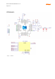
DC/DC regulator output. Connect to inductor
when internal DC/DC regulator is used
1
, leave
unconnected otherwise
SWDIO
SWDIO
Digital I/O
Serial wire debug I/O for debug and
Programming
SWDCLK
SWDCLK
Digital input
Serial wire debug clock input for debug and
programming
1 See nRF52832 datasheet [2] for reference circuit and layout recommendations
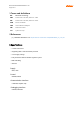
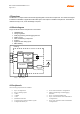
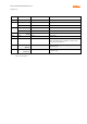
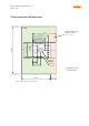
Table 1 Pin description
Blum 23.A00L83 RF Module Manual 1.0.2
Page 9 of 17
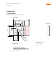
GND
WKUP
SWDIO
SWDCLK
VDD