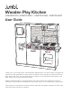
® Wooden Play Kitchen JUMWODKTCH, JUMKTCHPNK1, JUMKTCHPNK2, JUMKTCHWHIT User Guide Thank you for purchasing the Jumbl Wooden Play Kitchen. This User Guide is intended to provide you with guidelines to ensure that operation of this product is safe and does not pose risk to the user. Any use that does not conform to the guidelines described in this User Guide may void the limited warranty. Please read all directions carefully before using the product and retain this guide for reference.
Safety Precautions WARNING Please read all safety precautions and instructions carefully before using this product. Failure to properly follow the guidelines established here could result in serious injury. This product is not recommended for children under 3 years old. WARNING Choking hazard – small parts associated with this product are a choking hazard for children under 3 years old. • Adult setup is required to assemble this product safely. • Remove all packaging before using this product.
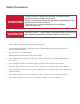
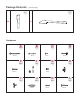
Package Contents 1PC 1PC 5 1 6 7 1PC 1PC 1PC 1PC 8 1PC 2 9 1PC 1PC 3 10 1PC 1PC 4 11
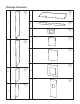
Package Contents 2PCS 12 (continued) 19 20 1PC 21 1PC 1PC 1PC 1PC 22 23 13 24 2PCS 1PC 2PCS 14 1PC 25 1PC 15 1PC 1PC 26 16 1PC 1PC 17 27 18 1PC
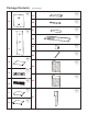
Package Contents (continued) 1PC 1PC 29 28 Hardware A B 34PCS 42 mm C 2PCS 32 mm E 8PCS 9 mm F 22PCS 2PCS 25 mm G 4PCS 20 mm D H 16PCS 5PCS 9 mm I J 5PCS K 27PCS 30 mm L 4PCS 18 mm 2PCS 28 mm
Package Contents (continued) Accessories 1PC 1PC 1PC 1PC 1PC 1PC 1PC 1PC 4PCS 4PCS 4PCS 4PCS 1PC Recommended Tools • Philips head screwdriver (not included) • Wrench (included)
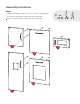
Assembly Instructions Step 1 • Fasten all handles to doors 7, 8, 9, 10, and 11 using two (2) E screws on each door. Orient each door as shown. Door 7 uses a different handle than the other doors.
Step 2 • Fasten the chalkboard to door 8 using four (4) C screws. • Fasten the ice dispenser to door 11 using four (4) C screws.
Step 3 • Fasten one (1) I latch to each of the five (5) doors using two (2) G screws on each door.
Step 4 • Fasten two (2) H latches to panel 2 and one (1) H latch to panel 29 as shown. Use G screws to fasten.
Step 5 • Fasten one (1) H latch to each side of panel 3 using two (2) D screws. Use the provided wrench to hold the nut in place as you tighten the screws.
Step 6 • Mount the four (4) dials onto panel 16 using four (4) K screws. Make sure the inner piece of the dial fits into the lower holes on panel 16 and that the dial spins after tightening the screws.
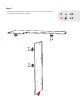
Step 7 • Insert one (1) wooden dowel into panel 6 and attach it to panel 5. • Then, insert four (4) additional dowels into the sides of panel 6.
Step 8 • Fasten panel 1 to panel 5 using two (2) A screws while aligning the dowels from panel 6 into panel 1. A Make sure the back grooves of panels 1 and 5 are aligned and that the hinges on panel 5 are facing up.
Step 9 • Fasten panel 4 to panel 5 using two (2) A screws while aligning the dowels from panel 6 into panel 4. A Make sure the back grooves on panels 4 and 5 are aligned.
Step 10 • Fasten panel 2 to panel 5 using two (2) A screws. Make sure latches on panel 2 are facing panel 1 and the back grooves on panel 2 align with panel 5.
Step 11 • Fasten panel 3 to panel 5 using two (2) A screws. Make sure the back grooves on panel 3 align with panel 5.
Step 12 • Insert backboards 12 and 13 into their respective slots.
Step 13 • Fasten two (2) shelf holders on opposite sides of panel 3 using two (2) B screws. Be sure to use the inner screw holes on the shelf holders.
Step 14 • Fasten one shelf holder each on panel 2 and panel 4 using two (2) E screws each. Be sure to use the inner screw holes on the shelf holders.
Step 15 • Insert shelves 14 into their respective slots.
Step 16 • Mount panel 17 between panels 1 and 2 on the bottom-most screw holes using four (4) A screws. Ensure the smooth side is facing up on panel 17.
Step 17 • Mount panels 23 to the outside of panel 4 using four (4) A screws.
Step 18 • Unscrew one end of towel rack 24, pass the rack between panels 23, and reattach the end to lock in place.
Step 19 • Align doors 9 and 10 into the hinges on panel 5.
Step 20 • Connect panel 15 to panel 2 with the icons facing out. • Use a dowel for the upper connection and fasten one (1) A screw for the lower connection.
Step 21 • Insert two (2) dowels into panel 15 through the holes on panel 3. • Push these entirely through.
Step 22 • Insert two (2) dowels into panel 16 and align the panel into the holes on panel 3. • Attach panel 16 to panel 4 using one (1) dowel for the upper connection and one (1) A screw for the lower connection.
Step 23 • Fasten faucet to countertop using two (2) L screws.
Step 24 • Mount the four (4) stovetop burners to the countertop using eight (8) E screws.
Step 25 • Fasten panels 27 and 28 to the countertop with one (1) A screw each. A Make sure that the back grooves are aligned. Panel 27 will have back grooves on both sides while panel 28 will only have a back groove on one side.
Step 26 • Screw four (4) F cam lock screws into the bottom of the countertop.
Step 27 • Align the four (4) F cam lock nuts into the holes on panels 3 and 4.
Step 28 • Align the countertop onto the main assembly with the four (4) F cam lock screws lining up with the holes on panels 3 and 4. • Once aligned, give each F cam lock nut a half turn to lock in place.
Step 29 • Fasten two (2) A screws to the countertop through the holes on panel 2.
Step 30 • Insert panels 25 and 26 into their respective slots. Make sure the grey area on panel 26 is facing up.
Step 31 • Attach panel 18 to panels 1 and 2 by the back two (2) A screws only. Make sure the smooth side of panel 18 is facing up, and the hinge is on the front left side.
Step 32 18 • Align door 11 between the hinges on panel 5 and panel 18. • Then, fasten panel 18 in place using the front two (2) A screws to mount the door in place.
Step 33 • Insert four (4) dowels into panel 20 and connect it to panels 27 and 28.
Step 34 • Mount panel 19 using four (4) dowels and two (2) A screws between panels 27 and 28 with the hinge facing up on the right-hand side. Panel 20 may slide while mounting. Be sure panel 20 is in the proper place before tightening the final A screw on panel 19.
Step 35 • Align door 7 and the microwave control panel with the hinge and slots on panel 19.
Step 36 • Attach panel 21 between panels 2 and 27 using four (4) wooden dowels.
Step 37 • Align door 8 with the hinge on panel 18.
Step 38 • Align panel 29 with the hinges on door 7 and door 8. • Fasten panel 29 to the assembly using six (6) A screws. A Make sure the microwave control panel slots into the grooves on panel 29.
Step 39 • Drop the sink in place, bring over the other accessories, and enjoy.
Limited Warranty to Original Consumer This Jumbl Wooden Play Kitchen (“Product”), including any accessories included in the original packaging, as supplied and distributed new by an authorized retailer is warranted by C&A Marketing, Inc.
(i) If any Jumbl Wooden Play Kitchen serial number has been removed or defaced. This Warranty is valid only in the country where the consumer purchased the Product, and only applies to Products purchased and serviced in that country. The Company does not warrant that the operation of the Product will be uninterrupted or error-free. The Company is not responsible for damage arising from your failure to follow instructions relating to its use.