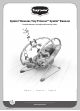
Gymini® Bouncer, Tiny Princess™ Gymini® Bouncer Portable bouncer with adjustable activity arches English - 1 | Français - 4 | Español - 7 For more developmental information and playing tips please visit: www.tinylove.
English Gymini® Bouncer, Tiny Princess™ Gymini® Bouncer Portable bouncer with adjustable activity arches Instruction Guide PLEASE KEEP THIS INSTRUCTION GUIDE AS IT CONTAINS IMPORTANT INFORMATION Read all instructions before using the infant bouncer seat (These instructions apply to Gymini® Bouncer and Tiny Princess™ Gymini® Bouncer) Product Key (Please refer to illustration below) A B C D E F G H I J Wire base frame (left) + reclining mechanism + anti-skid feet Wire base frame (right) + reclining mechan
B A C Fig. 1 Fig. 2 ck i “cl Fig. 3 ” “click Fig. 4 ” Fig. 5 Fig. 6 Fig. 7 Fig. 8 Fig. 9 Fig. 10 Fig. 11 Fig. 12 Fig. 13 Fig. 14 For disassembly instructions go to: www.tinylove.com/bouncer/disassembly.pdf Fig. 15 Fig. 16 For more developmental information and playing tips please visit: www.tinylove.com 2 © 2011. All rights reserved, Tiny Love Ltd.
Product Assembly Vibration Unit Battery Installation Assembling Bouncer Product assembly requires a Phillips screwdriver. Pull out the head rest tube from the seat pad and continue to assemble the product according to the instructions (Fig. A,B,C). 1. Attach the two wire base frames to the base tube as shown in the illustration. Make sure the rounded side of the base tube is arched outward (Fig. 1). 2.
Français Gymini® Bouncer, Tiny Princess™ Gymini® Bouncer Transat portable avec arches d’activités réglables Notice d’utilisation MERCI DE CONSERVER CETTE NOTICE D’UTILISATION QUI CONTIENT DES INFORMATIONS IMPORTANTES Lisez attentivement toutes les instructions avant de vous servir du transat (Cette notice est valable pour le Gymini® Bouncer and et le Tiny Princess™ Gymini® Bouncer) Légende (reportez-vous à l’illustration ci-dessous) A Socle en métal (gauche) + mécanisme d’inclinaison + pieds antidérapan
B A Fig. 1 C Fig. 2 ck i “cl Fig. 3 ” “click Fig. 4 ” Fig. 5 Fig. 6 Fig. 7 Fig. 8 Fig. 9 Fig. 10 Fig. 11 Fig. 12 Fig. 13 Fig. 14 Pour les instructions de démontage, rendez-vous sur : www.tinylove.com/bouncer/disassembly.pdf Fig. 15 Fig. 16 Pour de plus amples informations sur le développement et des conseils de jeu, rendez-vous sur : www.tinylove.com © 2011. Tous droits réservés, Tiny Love Ltd.
Montage du produit Installation des piles de l’unité de vibration Montage du transat Attention : Il vous faudra un tournevis cruciforme. Sortez la tubulure de l’appui-tête de la housse et poursuivez le montage conformément aux instructions (Fig. A,B,C). 1. Fixez les deux socles métalliques à la tubulure de base, comme indiqué dans l’illustration. Veillez à ce que le côté arrondi soit dirigé vers l’extérieur (Fig. 1). 2.
Español Gymini® Bouncer, Tiny Princess™ Gymini® Bouncer Asiento rebotador portátil con arcos ajustables de actividades Guía de instrucciones CONSERVE ESTA GUÍA DE INSTRUCCIONES, YA QUE CONTIENE INFORMACIÓN IMPORTANTE Lea todas las instrucciones antes de usar el asiento rebotador para niños (Estas instrucciones son válidas para los Gymini® Bouncer y Tiny Princess™ Gymini® Bouncer) Contenido del producto (ver la ilustración que se presenta a continuación) A Estructura base (izquierda) de alambre + mecanis
B A Fig. 1 C Fig. 2 ck i “cl Fig. 3 ” “click Fig. 4 ” Fig. 5 Fig. 6 Fig. 7 Fig. 8 Fig. 9 Fig. 10 Fig. 11 Fig. 12 Fig. 13 Fig. 14 Para las instrucciones de desensamblado vaya a: www.tinylove.com/bouncer/disassembly.pdf Fig. 15 Fig. 16 Para más información sobre el desarrollo y sugerencias de juego, visite: www.tinylove.com 8 © 2011. Todos los derechos reservados, Tiny Love Ltd.
Instalación de las pilas de la unidad vibratoria Montaje del producto Montaje del asiento rebotador Tenga en cuenta que: para el montaje del producto se debe utilizar un destornillador Phillips. Tire del tubo del cabezal del asiento y continúe armando el producto de acuerdo con las instrucciones (Fig. A,B,C). 1. Fije las dos estructuras base de alambre al tubo base, tal y como se muestra en la ilustración. Asegúrese de que el lado redondeado del tubo quede hacia afuera (Fig. 1). 2.