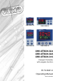
JUMO dTRON 316 JUMO dTRON 308 JUMO dTRON 308 JUMO dTRON 304 JdTRON 304 JdTRON 308 JdTRON 316 Compact Controller with program function B 70.3041.0 Operating Manual 06.
) Please read this Operating Manual before commissioning the instrument. Keep the manual in a place which is accessible to all users at all times. Please assist us to improve this operating manual. Your comments will be appreciated. Phone +49 661 6003-0 Fax +49 661 6003-607 All necessary settings are described in this operating manual. If any difficulties should still arise during start-up, please do not carry out any unauthorized manipulations on the unit.
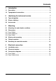
Contents 1 Introduction 5 1.1 Description .................................................................................................... 5 1.2 Typographical conventions ......................................................................... 6 2 Identifying the instrument version 2.1 Type designation .......................................................................................... 7 2.2 Scope of delivery ............................................................................
Contents 5 Operation 19 5.1 Displays and keys ....................................................................................... 19 5.2 Level concept ............................................................................................. 20 5.3 Level inhibit ................................................................................................. 20 5.4 Entries and operator prompting ............................................................... 21 5.
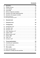
Contents 11 Retrofitting of modules 61 12 Appendix 63 12.1 Technical data ............................................................................................. 63 12.2 Alarm messages .........................................................................................
Contents
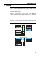
1 Introduction 1.1 Description The controller series consists of four freely programmable instruments in different DIN formats for controlling temperature, pressure and other process variables. The highcontrast, multicolor LCD display for process value, setpoint and operator prompting contains two four-digit 7-segment displays, two single-character 16-segment displays, display of the active setpoints, six status indicators, and displays for the unit, ramp function and manual operation.
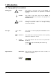
1 Introduction 1.2 Typographical conventions Warning signs V * E Note signs H v H Danger This symbol is used when there may be danger to personnel if the instructions are ignored or not followed correctly! Caution This symbol is used when there may be damage to equipment or data if the instructions are ignored or not followed correctly! Caution This symbol is used where special care is required when handling components liable to damage through electrostatic discharge.
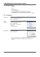
2 Identifying the instrument version 2.1 Type designation 703041 703042 703043 703044 Basic type Type 703041, format 48mm x 48mm incl. 1 analog input, 2 relay outputs and 2 binary inputs or 2 logic outputs Type 703042, format 48mm x 96mm (portrait format) incl. 1 analog and 2 binary inputs, 2 relays and 2 logic outputs Type 703043, format 96mm x 48mm (landscape format) incl. 1 analog and 2 binary inputs, 2 relays and 2 logic outputs Type 703044, format 96mm x 96mm incl.
2 Identifying the instrument version 2.2 Scope of delivery - 1 controller - 1 seal - mounting brackets - brief operating instructions - 1 CD including DEMO-software & operating manuals as pdf-file (Actual DEMO-software can be downloaded at www.JUMO.net. To enable DEMO-software to full rights, contact your local JUMO subsidiary.) 2.3 Accessories PC interface PC interface with TTL/RS232 converter and adapter (socket connector) for setup program Sales No.
3 Mounting 3.1 Mounting site and climatic conditions The conditions on the mounting site must meet the requirements specified in the technical data. The ambient temperature on the mounting site can be from 0 to 55 °C, with a relative humidity of not more than 90 %. 3.2 Dimensions 3.2.
3 Mounting Setup plug 3.2.2 Type 703042/43 3.2.
3 Mounting 3.3 Side-by-side mounting Minimum spacing of panel cut-outs Type horizontal without setup plug: 11mm 703041 (48mm x 48mm) 11mm 703042 (portrait format: 48mm x 96mm)) 30mm 703043 (landscape format: 96mm x 48mm) 11mm 703044 (96mm x 96mm) with setup plug (see arrow): 11mm 703041 (48mm x 48mm) 11mm 703042 (portrait format: 48mm x 96mm)) 65mm 703043 (landscape format: 96mm x 48mm) 11mm 703044 (96mm x 96mm) vertical 30mm 30mm 11mm 30mm 65mm 65mm 11mm 65mm 3.
3 Mounting 3.5 Removing the controller module The controller module can be removed from its housing for servicing. h Press together the knurled areas (top and bottom, or left and right for landscape format) and pull out the controller module. H 12 When inserting the controller module, make sure that the latches (below the knurled areas) snap into place.
4 Electrical connection 4.1 Installation notes - The choice of cable, the installation and the electrical connection must conform to the requirements of VDE 0100 “Regulations on the Installation of Power Circuits with Nominal Voltages below 1000 V” or the appropriate local regulations. - The electrical connection must only be carried out by qualified personnel. - If contact with live parts is possible while working on the unit, it must be disconnected from the supply on both poles.
4 Electrical connection 4.
4 Electrical connection 4.3 Connection diagrams 4.3.1 Type 703041 . V The electrical connection must only be carried out by specialist personnel. 1 2 3 1 2 3 4 5 6 7 8 1 2 3 4 L1(L+) 6 7 8 H The instrument version can be identified by the typecode.
4 Electrical connection 4.3.2 Type 703042/43/44 H . V The electrical connection must only be carried out by specialist personnel. 1 2 1 2 3 4 1 2 3 4 5 6 7 8 6 7 8 9 10 9 10 11 12 Terminal strip 3 16 3 L1(L+) N(L+) 4 5 6 8 9 11 12 13 15 16 17 The instrument version can be identified by the type code.
4 Electrical connection Terminal strip 2 Terminal strip 1 17
4 Electrical connection 18
5 Operation 5.
5 Operation 5.2 Level concept The parameters for making the settings on the instrument are arranged at different levels. H Time-out If no key is pressed for 30sec, the instrument returns to normal display. v Chapter 6 “Operator level” v Chapter 7 “Parameter level” v Chapter 8 “Configuration” v Setup/Display - Operation/Time-out 5.3 Level inhibit The access to the individual levels can be prevented.
5 Operation 5.4 Entries and operator prompting Entering values When entries are made within the levels, the parameter symbol is shown in the lower display. Select parameter Alter parameter P I/D IIIII IIIII IIIIIIIIIIIIIIIII I D IIIIIIII IIIIIIII h Select parameter with I or D h Change to entry mode with P (lower display blinks!) h Alter value with I and D The value alters dynamically with the duration of the key stroke.
5 Operation 5.5 Operation of the fixed-setpoint controller Normal display Manual mode Altering the setpoint In normal display: Manual mode In manual mode, the controller output can be altered by hand. h Alter the present setpoint with I and D (the value is accepted automatically) h Change to manual mode with X (press for more than 2 seconds) The output appears in the lower display. The hand symbol and the unit “%” light up in addition.
5 Operation 5.6 Operation of the program controller Normal display Program is running Altering the setpoint Program pause Normal display No program run in normal display, the controller controls to the selected setpoint.
5 Operation 5.6.1 Entering programs Function A setpoint profile can be implemented with a maximum of 8 program segments. Entry on the instrument The instrument must be configured as a program controller/generator. v Chapter 8.3 “Generator “Pro”” (Function) Configurable time base: mm:ss, hh:mm und dd:hh (s=seconds, m=minutes, h=hours, d=days). v Chapter 8.3 “Generator “Pro”” (unit) The segment setpoints (SPP1 — SPP8) and segment times (tP1 — tP8) are set at the operator level (program data).
5 Operation The program segments (up to eight) are defined by the segment setpoint and the segment time. P P IIIII IIIII IIIIIIIIIIIIIIIII I D IIIIIIII IIIIIIII D P I IIIII IIIII IIIIIIIIIIIIIIIII D IIIIIIII IIIIIIII D P IIIII IIIII IIIIIIIIIIIIIIIII I D IIIIIIII IIIIIIII D P IIIII IIIII IIIIIIIIIIIIIIIII I D IIIIIIII IIIIIIII Entry through setup program The setup program (accessory) features a user-friendly program editor, with a graphical presentation of the program profile.
5 Operation 5.6.2 Shifting the program profile The function “External setpoint with correction” can be used to shift the program profile upwards or downwards (configurable through the setup program only). The external setpoint is defined via an analog signal. v Chapter 8.
6 Operator level Access Process data “Proc” The four setpoints are displayed and edited here, and additional process variables are shown in accordance with the configuration.
6 Operator level Definition of the program times w (1) (3) (2) (4) tx User data “USEr” t (1) Program time (3) Segment time (2) Residual program time (4) Residual segment time Any number of parameters (up to eight) can be displayed and edited here using the setup program. v Setup/Configuration level/Display - Operation/User data The user himself can assign the symbol that is to be displayed for each parameter. Otherwise the standard symbol is used.
7 Parameter level General Two parameter sets (PAr1 and PAr2) can be stored. Access The level can be inhibited. Applications - Parameter set switching via binary function v Chapter 8.
7 Parameter level P A r A ➔ P A r 1 ( PAr2 ) Parameter Display Proportional band PB 1 Pb 2 Value range ! Meaning 0…9999 Factory setting 0 0…9999 0 The gain of the controller decreases with increasing proportional band. Size of the proportional band With Pb 1,2 = 0 the controller structure is ineffective (limit comparator response). Derivative time Reset time dt rt 0…9999 s 0…9999 s 80 s 350 s Actuator time tt 5…3000 s 60 s Cycle time CY1 CY2 0.0…999.9s 20 s 0.0…999.
8 Configuration General The following applies to the representation of parameters and functions at the configuration level: The parameter is not displayed or can not be selected if - the equipment level does not permit the function assigned to the parameter. Example: Analog output 2 can not be configured if analog output 2 is not implemented in the instrument. H Some parameters can only be programmed through the setup program. These are marked in the symbol column with “(setup)”.
8 Configuration Analog selector With some parameters, you can choose from a series of analog values. To provide you with an overview, this selection is listed below.
8 Configuration 8.1 Analog inputs “InP” Configuration Analog inputs Controller Generator Limit comparators Outputs Binary functions Display Timer Interfaces Depending on the instrument version, up to two analog inputs are available.
8 Configuration Analog input 1 InP1 ➔ Analog input 2 InP2 ➔ Measurement offset Symbol Value/selection OFFS -1999… 0… +9999 The measurement offset is used to correct a measured value by a certain amount upwards or downwards. Description Examples: Measured value offset Displayed value 294.7 295.3 +0.3 - 0.3 295.0 295.0 A The controller uses the corrected value (= displayed value) for its calculation. This value is not the same as the actually measured value.
8 Configuration Analog inputs (general)I n1 2 ➔ Symbol Temperature unit Unit Value/selection Description 0 deg. Celsius 1 deg. Fahrenheit Unit for temperature values Sampling cycle time CycL Supply frequency (setup) 0 1 2 3 50msec 90msec 150msec 250msec 50Hz Adaptation of the conversion time of the input circuitry to the 60Hz supply frequency Factory settings are shown bold.
8 Configuration Procedure Apply two measurement points ((1), (3)), one after another, to the controller; they should be as far apart as possible. At these measurement points, enter the required display value (start value FtS, end value FtE) in the controller. A reference instrument is most convenient for determining the measured values M1 and M2. Measurement conditions must remain stable during programming.
8 Configuration 8.2 Controller “Cntr” Configuration Analog inputs Controller Generator Limit comparators Outputs Binary functions Display Timer Interfaces The following are set here: controller type, input variables of the controller, the setpoint limits, conditions for manual mode and the presettings for autotuning (selfoptimization).
8 Configuration Symbol Value/selection Description Inputs Controller process value CPr (analog selector) Analog inp. 1 Defines the source for the process value of the control channel. v See “Analog selector” on Page 32. External setpoint ESP (analog selector) switched off Activates the external setpoint input and defines the source for the external setpoint. v See “Analog selector” on Page 32.
8 Configuration 8.3 Generator “Pro” Configuration Analog inputs Controller Generator Limit comparators Outputs Binary functions Display Timer Interfaces The basic function of the instrument is defined here. The instrument can be operated as a fixed-setpoint controller with or without a ramp function, or warm-up ramp for hot-channel equipment, program controller or program generator.
8 Configuration Ramp slope Tolerance band Symbol Value/selection Description rAS L toLP 0…9999 Value of slope for ramp function 0…999 0=off For a program controller/generator and ramp function, the process value can be monitored by applying a tolerance band around the setpoint profile. If the upper or lower limit is infringed, a tolerance limit signal is generated, which is internally processed or produced via an output. Processing the tolerance limit signal, see: v Chapter 8.
8 Configuration Hot-channel controller The warm-up ramp for hot-channel equipment is used, for example, for the gentle operation of ceramic heater elements. Damage can be avoided by allowing moisture to evaporate slowly from the hygroscopic heater elements during the warm-up phase (t0— t2). The present setpoint is accepted as the start value for the ramp at time t0. Within the time period t0 — t1, the programmed ramp slope rASL is used to approach the hold setpoint SPP2.
8 Configuration 8.4 Limit comparators “LC” Configuration Analog inputs Controller Generator Limit comparators Outputs Binary functions Display Timer Interfaces Limit comparators (threshold monitors, limit contacts) can be used to monitor an input variable (process value for the limit comparator) against a fixed limit or another variable (the setpoint for the limit comparator). When a limit is exceeded, a signal can be output or an internal controller function initiated.
8 Configuration In the case of the limit comparator functions lk7 and lk8, the measurement that is set is monitored with respect to a fixed value AL.
8 Configuration Limit comparator 1 Limit comparator 2 Limit comparator 3 Limit comparator 4 Symbol Action/ range response LC1 LC2 LC3 LC4 ➔ ➔ ➔ ➔ Value/selection Description 0 1 2 3 AcrA absolute/off relative/off absolute/on relative/on Action: Defines the switching action of the limit comparators on a setpoint change or power-on. absolute: At the time of alteration, the limit comparator acts according to its function. relative: The limit comparator is in the OFF status.
8 Configuration Limit comparator 1 Limit comparator 2 Limit comparator 3 Limit comparator 4 Symbol Acknowledgement LC1 LC2 LC3 LC4 Value/selection ➔ ➔ ➔ ➔ Description 0 no acknowledgement 1 acknowledgement; only with inactive limit comparator 2 acknowledgement; always possible Acn L For settings with acknowledgement, the limit comparator is latching, which means it remains ON, even when the switchon condition is no longer present. The limit comparator must be reset via the D + X keys or binary signal.
8 Configuration 8.5 Outputs “OutP” Configuration Analog inputs Controller Generator Limit comparators Outputs Binary functions Display Timer Interfaces Configuration of the instrument outputs are subdivided into analog outputs (OutA; max. 2) and binary outputs (OutL; max. 9). Binary outputs are relay, solid-state relay and logic outputs. Display and numbering of the outputs depends on the assignment of the option slots.
8 Configuration Binary outputs Symbol Binary output 1 0ut1 ... ...
8 Configuration Analog outputs 0utA ➔ Output 5 Output 6 Output 7 0ut5 ➔ 0ut6 ➔ 0ut7 ➔ Symbol Value/selection Description Function Fnct (analog selector) switched off Function of the output v See “Analog selector” on Page 32.
8 Configuration 8.6 Binary functions “binF” Configuration Analog inputs Controller Generator Limit comparators Outputs Binary functions Display Timer Interfaces Functions are assigned here to the binary signals of the binary inputs and limit comparators. In addition, the functions for control contacts, tolerance limit signal and program end signal are defined for program controllers/generators. In the case of a fixed-setpoint controller, functions can be assigned to the ramp end signals.
8 Configuration Symbol Binary input 1 Value/selection b in1 ... Binary input 8 Limit comparator 1 b in8 LC1 ... Limit comparator 4 Timer 1 Timer 2 Logic 1 Logic 2 Control contact 1 LC4 tF1 tF2 Lo 1 Lo 2 CC1 ...
8 Configuration The states Z1 and Z2 are assigned to the binary functions in descending order (see list on the right), i. e. the first binary function selected in the list is Z1. * only for program controller/generator Example: The setpoint is to be selected via a binary input and the state of one limit comparator.
8 Configuration 8.7 Display “diSP” Configuration Analog inputs Controller Generator Limit comparators Outputs Binary functions Display Timer Interfaces Symbol Value/selection Description General Upper display d iSU (analog selector) Displayed value for the upper display controller process v See “Analog selector” on Page 32. value Lower display d iSL (analog selector) Displayed value for the lower display controller setpoint v See “Analog selector” on Page 32.
8 Configuration 8.8 Timer “tFct” Configuration Analog inputs Controller Generator Limit comparators Outputs Binary functions Display Timer Interfaces Time-dependent control actions can be carried out with the help of the timer. The timer signal (timer 1+ 2) shows whether the timer is active. It can be output via the binary outputs or processed internally. The timers are started or canceled via the binary functions. v Chapter 8.
8 Configuration 8.9 Interfaces “IntF” Configuration Analog inputs Controller Generator Limit comparators Outputs Binary functions Display Timer Interfaces Configuration The interface parameters for the RS422/485 or Profibus-DP interface have to be configured in order to communicate with PCs, bus systems and peripheral devices.
9 Tuning (optimization) 9.1 Autotuning (self-optimization) Oscillation method Autotuning (self-optimization, SO) establishes the optimum controller parameters for a PID or PI controller.
9 Tuning (optimization) H With output type “solid-state”, the cycle time during autotuning is reduced to 8 x the sampling cycle time. With the “relay” output type, care has to be taken that the process value is not influenced by the cycle time, since otherwise autotuning can not be completed successfully. Solution: Reduce the cycle time Cy, until the process value is no longer influenced.
9 Tuning (optimization) Start of autotuning during operation h Start with I and D (simultaneously >2sec “tUnE” is shown, blinking, in the lower display H IIIII IIIIIIIIIIIIIIIII IIIII Autotuning is ended when the display automatically changes over to normal display. The duration of autotuning depends on the control process. IIIIIIII IIIIIIII Starting autotuning The controller output types have to be defined for autotuning. v Chapter 8.
9 Tuning (optimization) 9.2 Check of the tuning The optimum adaptation of the controller to the process can be checked by recording the approach phase with the control loop closed. The diagrams below indicate possible maladjustments and how these can be corrected. The control response of a third-order control loop for a PID controller is shown as an example. However, the procedure for adjusting the controller parameters can also be applied to other control loops.
10 Extra codes 10.1 Math and logic module The setup program can be used to implement two mathematical calculations or logical combinations of various signals and process variables from the controller in a formula. With math formulae, the calculated result is presented through the two signals “Math 1” and “Math 2” in the analog section. With logic formulae, the result of the logical combination is presented through the signals “Math 1” and “Math 2” of the configuration for binary functions. Chapter 8.
10 Extra codes Humidity control The humidity controller receives the process value from a psychrometric humidity probe, through the mathematical combination of wet bulb and dry bulb temperatures. RELF (E1, E2) E1 - Dry bulb temperature, via analog input 1 E2 - Wet bulb temperature, via analog input 2 Difference control The difference between the two input signals is taken as the process value.
11 Retrofitting of modules The following steps are necessary for retrofitting modules: Safety notes A Retrofitting must only be carried out by qualified professional persons. V changes, the back panel and the fixing screws are correctly For safety reasons, care must be taken that, after making the replaced and fitted. E Identifying the module Removing the controller module The modules can be damaged by electrostatic discharge. So avoid electrostatic charge during fitting and removal.
11 Retrofitting of modules h Select the slot for the option (Observe the restrictions for Type 703041! (see connection diagram)) On Type 703041, relays can only be retrofitted in option slot 1! Option 3 H Type 703042/43/44 Option 1 Option 2 Option 1 Type 703041 Option 2 Retrofitting of modules h Push the module into the slot until the plug connector snaps into place h Push the module into the housing until the lugs snap into their slots 62
12 Appendix 12.
12 Appendix Measuring circuit monitoring In the event of a fault, the outputs move to a defined (configurable) status.
12 Appendix Electrical data Supply voltage (switchmode PSU) 110 — 240V AC -15/+10%, 48 — 63Hz 20—53V AC/DC, 48—63Hz Electrical safety Power consumption Data backup Electrical connection Electromagnetic compatibility interference emission interference immunity to EN 61 010, Part 1 Overvoltage category II, pollution degree 2 for type 703041 with power supply AC/DC connect to SELV and PELV only max. 7VA EEPROM at the back, via screw terminals, conductor cross-section up to 1.
12 Appendix 12.2 Alarm messages Display Cause Fault removal test/repair/replace Underrange for the value being Is the medium being measured within the -1999 displayed. range (too hot? too cold?) (blinking!) Check probe for short-circuit and probe Overrange for the value being break 9999 displayed. (blinking!) Check the probe connection and the terminals. Check the cable. all displays on; Watchdog or power-on trigger Replace the controller if the initialization initialization (reset).
13 Index A H Access code 31 Accessories 8 Acknowledgement 45 Analog input 33 Analog marker 54 Analog selector 32 Autotuning (self-optimization) 38, 55 Heater current monitoring 34 Hot-channel controller 41 Humidity control 60 B Baud rate 54 Binary functions 49 Binary marker 54 Binary output 47 Brightness 52 C Commissioning 2 Connection diagrams 15 Control action 37, 53–54 Control contacts 40 Controller 37 Controller module, removing 12 Controller standby output 38 Controller type 37, 47, 50, 53 D Data
S T Safety notes 61 Sampling cycle time 35 Scope of delivery 8 Sensor type 33 Setpoint 27 external 38 Setpoint limits 37 Setpoint switching 50 Setup program 8 Side-by-side mounting 11 Signal type 48 Step response method 55 Step size 38 Supply frequency 35 Switching action 49 Switching differential 43 Switch-on delay 44 Text display 50 Time-out 52 Tolerance band 40, 53 Tuning (optimization) 58 Type designation 7 U Unit 35, 39 User data 28 W Warranty 2 Z Zero point 48 68
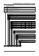
Overview of the configuration level InP1 InP2 SEnS Lin OFFS SCL SCH dF FtS FtE HEAt Sensor type Linearization Measurement offset Display start Display end Filter time constant Fine tuning start value Fine tuning end value Heater current monitoring InP12 Unit CYcL Temperature unit Sampling cycle time Cntr CtYP CAct InHA HAnd rOut SPL SPH CPr ESP FEEd tYPt InHt Ott1 Ott2 SOut StSI Controller type Control action Inhibit manual mode Manual output Range output Setpoint low Setpoint high Controller proces
JUMO GmbH & Co. KG JUMO Instrument Co. Ltd. JUMO PROCESS CONTROL INC. Street address: Moltkestraße 13 - 31 36039 Fulda, Germany Delivery address: Mackenrodtstraße 14 36039 Fulda, Germany Postal address: 36035 Fulda, Germany Phone: +49 661 6003-0 Fax: +49 661 6003-607 e-mail: mail@jumo.net Internet: www.jumo.net JUMO House Temple Bank, Riverway Harlow, Essex CM20 2TT, UK Phone: +44 1279 635533 Fax: +44 1279 635262 e-mail: sales@jumo.co.uk Internet: www.jumo.co.