
Instructions

10 Appendix
68
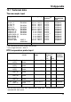
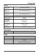
RTD temperature probe input (continued)
Standard signals input
3
The accuracy refers to the max. measurement range span. The linearization accuracy is
reduced with short spans.
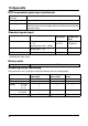
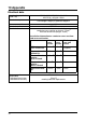
Binary inputs
Measuring circuit monitoring
In the event of a fault, the outputs change to defined statuses (configurable).
Sensor lead
resistance
max. 30
Ω
per lead for 3-wire/4-wire circuit
Measuring current approx. 250µA
Lead compensation Not required for 3-wire and 4-wire circuit. For a 2-wire circuit, the
lead resistance can be compensated in the software by correcting
the actual value.
Designation Measuring range Measuring
accuracy
3
Ambient
temperature
error
Voltage 0(2)—10V
0—1V
Input resistance R
IN
> 100k
Ω
≤
0.05%
≤
0.05%
100ppm/K
100ppm/K
Current 0(4)—20mA
Voltage drop
≤
1.5V
≤
0.05% 100ppm/K
Resistance transmitter min. 100
Ω
, max. 4k
Ω±
4
Ω
100ppm/K
Floating contacts open = inactive; short-circuited to GND = active
Sensor Measuring overrange /
underrange
Probe or lead
short-circuit
Probe or lead
break
Thermocouple • - •
RTD temperature probe • • •
Voltage 2—10V
0—10V
0—1V
•
•
•
•
-
-
•
-
-
Current 4—20mA
0—20mA
•
•
•
-
•
-
Resistance transmitter - - •
• = detected - = not detected