Series ATH.-SE-.. Surface-mounting thermostats B 603031.
Please read these Operating Instructions before commissioning the instrument. Keep the operating instructions in a place which is accessible to all users at all times. Please assist us to improve these operating instructions. Your suggestions will be welcome. Phone +49 661 6003-0 Fax +49 661 6003-607 All necessary settings and, where appropriate, alterations inside the instrument are described in these operating instructions.
Contents Page 1 Introduction ............................................................................... 5 1.1 1.1.1 1.1.2 Typographical conventions ...................................................................... 5 Warning signs .............................................................................................. 5 Note signs ................................................................................................... 5 1.2 Application .......................................
Contents Page 5 Settings .................................................................................... 18 5.1 Setting the limit value ............................................................................. 18 5.2 Resetting the STB ................................................................................... 19 5.3 5.3.1 5.3.2 Self-monitoring ........................................................................................
1 Introduction 1.1 Typographical conventions 1.1.1 Warning signs V Danger A 1.1.2 H v abc1 This symbol is used where there may be danger to personnel if the instructions are disregarded or not followed accurately. Caution This symbol is used where there may be damage to equipment if the instructions are disregarded or not followed accurately. Note signs Note This symbol is used to draw your special attention to a remark.
1 Introduction 1.2 Application Surface-mounting thermostats Series ATH.-SE-.. are approved for monitoring installations on steel-hulled ocean-going ships (e.g. steam and boiler plant, indirect heating systems) as: ❏ Temperature monitor (TW) ❏ Safety temperature monitor STW (STB) ❏ Safety temperature limiter (STB).
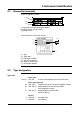
2 Instrument identification 2.1 Nameplate (example) on the case bottom section: (1) (2) (3) (1) Type code (see type designation, below) (2) Control range / contact rating (3) Approval mark on the thermostat case (inner section): (6) (1) (2) (4) 1315 (5) (7) ( 1 ) Type ( 2 ) Type code ( 4 ) Fabrication number ( 5 ) Year of manufacture ( 6 ) Week of manufacture ( 7 ) Connection diagram 2.2 Type designation Type code 603031 02 20 70 1 2 Basic type ATH.
3 Mounting 3.1 Dimensions 33 70 66 ATHs-SE-2, ATHs-SE-20 with sheath "20" (up to +150 °C) S = max.
3 Mounting K M24x1,5 M 20x1,5 DIN 89280-Z14 Ø 90 ~85 70 66 ATHs-SE-2 (20) with sheath "30" (up to +300 °C) S = max. 200 (150) 14 27 G 1/2 Ø 26 Ø 33 70 66 12 ATHf-SE-70, with sheath "20" (up to +300 °C) Ø Ø 26 14 27 G1/2 G1/2 94 S = max.
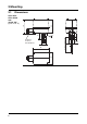
3 Mounting 3.2 Opening the case Opening ✱ Unscrew the two lead-sealable cheese-head screws ( 5 ) ✱ Remove the upper part of the case ( 1 ) (5) (5) (1) V 3.3 Ensure that the gasket is seated correctly when reassembling! Fixing the surface-mounting thermostat Operating position 3.3.1 unrestricted (for open-air mounting on request) Code s (rigid stem) The case journal is secured in the enlarged open end of the sheath by two fixing screws. 3.3.
3 Mounting 3.4 Capillary / temperature probe / sheath 3.4.1 General A Cutting through or kinking the capillary will lead to permanent failure of the instrument! Minimum permissible bending radius of the capillary is 5 mm. The temperature probe must be fitted in a JUMO sheath, otherwise the approval of the surface-mounting thermostat becomes invalid. H The temperature probe must be completely submerged in the medium.
3 Mounting 3.5 Permissible pressure at the sheath 3.5.1 Sheaths 20 and 30 A 3.5.1.1 The following values refer to the maximum pressure of the probe mounting concerned. The maximum pressure which can be sealed depends on the mounting conditions and may possibly be lower. Stainless steel sheath Material l Tube and nipple material: X 6 CrNiMoTl 17 122 Temperature Permitted flow velocities 3.5.1.2 Tube diameter 8 x 0.75 mm or conical 10 x 0.75 mm Max. permissible pressure Max.
3 Mounting 3.6 H Mounting the probe Submerge the sheath and the temperature probe (2) into the medium and ensure that the temperature probe (2) is completely submerged in the medium because otherwise, greater switching point deviations will occur. For thermostats with longdistance line (abbreviation "f"), the temperature probe is fastened in the sheath by means of the clamping piece (1) for connection types "20".
4 Installation 4.1 V Regulations and notes ❏ The electrical connection must only be made by qualified personnel. ❏ The choice of cable, the installation and the electrical connection must conform to the requirements of VDE 0100 “Regulations for the installation of power circuits with nominal voltages below 1000 V”, or the appropriate local regulations. ❏ If contact with live parts is possible while working on the unit, it must be completely disconnected from the supply.
4 Installation 4.2 Electrical connection ✱ Open the case. ➈ Section 3.2 “Opening the case”, page 10. ✱ Pass the connection cable (cable diameter 10 — 16,5 mm) through the screw connection (3). Fitting type"X" (no special tools), screw connection up to 2.5 mm2 conductor cross-section. ✱ Remove the protective cover ( 4 ). ✱ Establish the connection to the terminals ( 1 ) in accordance with the appropriate connection diagram. ✱ Connect the protective conductor to terminal PE ( 2 ).
4 Installation Connection diagrams TW / STW (STB) 4.2.1 STB as N/C contact with signal contact STB with (N/C) break contact Closing the case ✱ Make sure that the plastic gasket in the lower part of the case ( 2 ) is seated correctly. H On thermostats with code -70, the external reset button ( 3 ) must be located precisely on top of the internal reset button ( 4 ) for the microswitch, since this is the only way the reset button ( 3 ) can be operated from the outside.
4 Installation Cable relief ✱ Turn the screw connection ( 1 ) clockwise until the cable inlet is sealed and the cable is secured against pulling out. The cable has to be protected against vibration overload by leaving sufficient extra cable length ( 2 ). ✱ Close the case.
5 Settings 5.1 Setting the limit value ✱ Open the case. ➈ Section 3.2 “Opening the case”, page 10. ✱ Set the limit value on the set point setter ( 5 ) using a screwdriver.
5 Settings 5.2 Resetting the STB After the temperature has fallen below the set limit value (safe temperature limit) by about 10% of the scale range, the microswitch can be reset. Action 1. 2. 3. ✱ Unscrew the cap nut (1). ✱ Press the reset but✱ Screw the cap nut (1) ton (2) until the micro back on switch is reset. 5.3 Self-monitoring 5.3.1 Behaviour in the event of a measuring system breakage H 5.3.
6 Instrument description 6.1 Technical data Permissible ambient temperature in operation Capillary Thermostat head +80 °C +80 °C -40 °C -40 °C below +200°C -20 °C -20 °C > 200 °C to < 350 °C maximum minimum with scale limit value Permissible overtemperature safety on the probe during use Permissible storage temperature maximum +50 °C, minimum -50 °C Case Cover: aluminium die casting with screws for lead sealing max.
6 Instrument description Operating mode as per EN 60 730-1 TW: Type 2BL = automatic mode with microswitch disconnection in operation, which requires no auxiliary energy source. STB, STW (STB): Type 2BK = automatic mode with microswitch disconnection in operation, with fail-safe facility. Operating position unrestricted (with open-air mounting on request) Weight approx. 0.
JUMO GmbH & Co. KG JUMO Instrument Co. Ltd. JUMO Process Control, Inc. Street address: Moritz-Juchheim-Straße 1 36039 Fulda, Germany Delivery address: Mackenrodtstraße 14 36039 Fulda, Germany Postal address: 36035 Fulda, Germany Phone: +49 661 6003-0 Fax: +49 661 6003-607 E-mail: mail@jumo.net Internet: www.jumo.net JUMO House Temple Bank, Riverway Harlow - Essex CM20 2DY, UK Phone: +44 1279 63 55 33 Fax: +44 1279 63 52 62 E-mail: sales@jumo.co.uk Internet: www.jumo.co.