ATH-EXx Explosion-protected surface-mounted thermostat for potentially explosive gas atmosphere Zone 1 and potentially explosive dust atmosphere Zone 21 B 605051.
Please read these Operating Instructions before commissioning the instrument. Keep the manual in a place that is accessible to all users at all times. Please assist us to improve these operating instructions, where necessary. Your suggestions will be appreciated. Phone+49 661 6003-0 Fax +49 661 6003-607 All necessary settings and, where appropriate, alterations inside the instrument are described in these operating instructions.
Contents Seite 1 Introduction ............................................................................... 5 1.1 1.1.1 1.1.2 Typographical conventions ...................................................................... 5 Warning signs .............................................................................................. 5 Note signs ................................................................................................... 5 1.2 1.3 1.4 Application ..............................
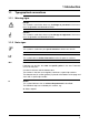
1 Introduction 1.1 Typographical conventions 1.1.1 Warning signs Danger This symbol is used when there may be danger to personnel if the instructions are ignored or not followed correctly! Caution This symbol is used when there may be damage to equipment if the instructions are ignored or not followed correctly! 1.1.2 Note signs Note This symbol is used when your special attention is drawn to a remark. Reference This symbol refers to further information in other chapters or sections.
1 Introduction 1.2 Application Depending on the version, the explosion-protected surface-mounting thermostat type ATH-EXx can be used as a ■ TW temperature monitor ■ TB temperature limiter ■ STW fail-safe temperature monitor ■ STB break-proof protection temperature limiter in areas with an explosion hazard caused by gases, vapors or mists, Zone 1 or in areas with combustible dust or dust/air mixtures, Zone 21.
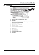
2 Instrument identification 2.1 Nameplate (8) (1) (2) (3) (4) (10) ( 12 ) ( 9 ) (11) (7) (5) (6) ( 1 ) Type ➩ Chapter 2.
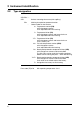
2 Instrument identification 2.2 Type designation ATH-EXx-. .- . ATH Surface-mounting thermostat (with capillary) ATH-EXx Marking for explosion-protected version ATH-EXx-. .- . Code number for the function: 2 =0Temperature monitor (TW) with changeover contact. Limit adjustable within the housing. 7 =0Temperature limiter (TB) with changeover contact and restart lock-out. Limit adjustable within the housing. 7-F =0Temperature limiter (TB) with changeover contact and restart lock-out. Limit is factory-set.
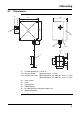
3 Mounting Dimensions 122 90 (2) 29 25 (3) (4) (6) (5) (7) 82 L ( 1.2 ) 6.4 ( 1.1 ) d 106 10.4 (1) 120 3.1 (1) Ex cable gland M 20 x 1.5 x 6-12 (1.1) Screw-in thread Tightening torque: 3,75 Nm (1.2) Compression screw Tightening torque: for cable dia. 06 mm = 3.5 Nm Tightening torque: for cable dia. 12 mm = 2.
3 Mounting 3.2 Opening the surface-mounting thermostat ✱ Unscrew the 4 cover screws (2) ✱ Remove cover (3) with seal (not visible) Make sure that the seal is seated correctly when reassembling! 3.3 Fixing the surface-mounting thermostat Mounting position To DIN 16257, NL 0 — NL 90 (other NL on request) ✱ Drill fixing holes according to the drilling diagram. ✱ Use the 4 screws to secure the housing base. 3.4 Capillary / temperature probe / pocket 3.4.
3 Mounting 3.5 Permissible operating conditions at the pocket 3.5.1 Probe mountings 20 and 22 The values given below refer to the maximum loading on the probe mounting concerned. The maximum pressure which can be sealed depends on the mounting conditions and may possibly be lower. 3.5.1.1 Steel pockets Materials Tube: Weld-in nipple: St 35.8 I 16 Mo 3 (no turned groove) Loading Temperature Tube diameter 8 x 0.75 mm or conical 10 x 0.75 mm 15 x 0.75 mm max. permissible pressure max.
3 Mounting Permissible incident flow velocity Temperature: Thermal medium: Tube diameter D: +200°C air (1) water, oil (2) 08 mm 10 mm 15 mm Permissible incident flow velocity “v” at the maximum permissible pressure loading and different immersion tube lengths “S” Permissible incident flow velocity “v” at the maximum permissible pressure loading and different immersion tube temperatures “t” 12
3 Mounting 3.5.1.2 Stainless steel pocket Materials Tube: Screw-in/weld-in nipple: X 6 CrNiMoTi 17122 X 6 CrNiMoTi 17122 Loading Temperature Permissible incident flow velocity 3.5.1.3 Tube diameter 8 x 0.75 mm or conical 10 x 0.75 mm 15 x 0.75 mm max. permissible pressure max. permissible pressure max.
3 Mounting 3.5.2 Probe mountings 10, 15, 21, 60, 65 Materials Choice of steel, stainless steel or brass Loading Only for use in unpressurized media. Probe mounting Maximum temperature 15 +55°C 60, 65 +200°C* 10, 21 +500°C* *depending on the control range 3.6 Mounting the probe The temperature probe (2) must be immersed in the medium for its entire length, otherwise there will be appreciable deviations from the switching point.
4 Installation 4.1 Regulations and notes In case of electrical connections in a potentially explosive area, it is necessary to comply with the relevant specifications. ■ The electrical connection must only be carried out by qualified personnel. ■ The choice of cable, the installation and the electrical connection must conform to the requirements of VDE 0100 “Regulations on the Installation of Power Circuits with Nominal Voltages below 1000 V” or the appropriate local regulations.
4 Installation 4.2 Electrical connection ✱ Open the housing. ➩ "Opening the surface-mounting thermostat", page 9 ✱ Pass the connection cable (cable diameter 6 to 12 mm) through the Ex cable compression gland (1). ➩ "Dimensions", page 8 ✱ Make the connection to the terminals (2) in accordance with the connection diagram. ✱ Fitting type X (no special tools). ✱ The connecting cable must have a fixed installation ✱ Connect the protective earth conductor to the PE terminal.
5 Settings 5.1 Limit setting 5.1.1 TW, STW, TB (code 7) ✱ Open the housing. ➩ "Opening the surface-mounting thermostat", page 9 ✱ Set the limit on the setpoint spindle (1). 05 5.1.2 °C (1) 05 STB (code 70) Important note for setup and operation! When the thermostat is used as a safety device for explosion protection in accordance with EU Directive 94/9/EC Annex II Sec. 1.5, a functional test is required that conforms to the applicable regulations.
5 Settings Setting the limits according to specific system characteristic ✱ Open the housing. ➩ "Opening the surface-mounting thermostat", page 9 ✱ Warm up the temperature probe – in the system – to the intended limit temperature (allow at least 5 minutes for the temperature to equalize), while using a calibrated reference measuring device to measure and observe the precise temperature at the temperature probe.
5 Settings 5.2 Resetting the TB or STB limiter If the temperature at the probe goes above the limit that has been set, the electrical circuit 1-4 is opened and remains mechanically locked out. When the critical temperature has fallen to about 9-15% below the set limit, the TB or STB can be reset manually. ✱ Open the housing. ➩ "Opening the surface-mounting thermostat", page 9 ✱ Press the reset arm ( 2 ) in the direction of the arrow. ➩ "( 2 ) reset arm", page 18 5.3 Self-monitoring (fail-safe) 5.3.
6 Instrument description 6.1 Technical data Ex marking II 2G Ex ed IIC T5 bzw. T6 for potentially explosive gas atmospheres II 2D Ex tD A21 IP65 T95°C bzw.
6 Instrument description Permissible ambient temperature in operation Capillary max. Thermostat head °C °C T6 +40 +40 T5 +55 +55 min. -20 (-50 et TZ 679) Max operating temperature of the cable screw-connection for the TZ 679: 70°C. Permissible probe temperature max. limit +15% (+550°C with limit > 450°C) Permissible storage temperature max. +50°C, min. -20°C Connecting cable diameter 6 to 12 mm, conductor cross-section up to 2.5 mm2 Switching differential in % of control/ limit range max.
6 Instrument description Enclosure protection EN 60 529 - IP 65 Operating medium Water, oil, air, superheated steam Time constant t0.632 Mode of operation in water in oil in air / superheated steam 45 s 60 s 120 s according to EN 60 730-1 TW,TB: Type 2BL = automatic action with micro-disconnection in operation, no auxiliary supply required. STW: Type 2BKL = automatic action with micro-disconnection in operation, fail-safe.
6 Instrument description Switching point accuracy in % of scale span, referred to the limit value at Ta +22°C. +0 TW, TB in upper third of scale -4 % +0 -6 % at start of scale +0 STW, STB in upper third of scale -5 % +0 -7 % at start of scale Mean ambient temperature effect in % of scale span, referred to the limit value.
7 Appendix 24
7 Appendix 25
7 Appendix 26
7 Appendix 27
7 Appendix 28
7 Appendix 29
7 Appendix 30
JUMO GmbH & Co. KG JUMO Instrument Co. Ltd. JUMO Process Control, Inc. Street address: Moritz-Juchheim-Straße 1 36039 Fulda, Germany Delivery address: Mackenrodtstraße 14 36039 Fulda, Germany Postal address: 36035 Fulda, Germany Phone: +49 661 6003-0 Fax: +49 661 6003-607 e-mail: mail@jumo.net Internet: www.jumo.net JUMO House Temple Bank, Riverway Harlow, Essex CM20 2TT, UK Phone: +44 1279 635533 Fax: +44 1279 635262 e-mail: sales@jumo.co.uk Internet: www.jumo.co.