JUMO dTRON 316 JUMO dTRON 308 JUMO dTRON 308 JUMO dTRON 304 JdTRON 304 JdTRON 308 JdTRON 316 JdTRON 304 plast JdTRON 308 plast Compact Controller with program function B 70.3041.2 Interface Description 07.
Contents 1 Introduction 5 1.1 Preface .......................................................................................................... 5 1.2 1.2.1 1.2.2 1.2.3 Typographical conventions ......................................................................... Warning signs ................................................................................................. Note signs ......................................................................................................
Contents 4 Data flow 21 5 Address tables 23 5.1 Process data ............................................................................................... 23 5.2 Setpoints ..................................................................................................... 25 5.3 Controller parameters ................................................................................ 25 5.4 Configuration ............................................................................................
1 Introduction 1.1 Preface Please read these operating instructions before commissioning the instrument. Keep the manual in a place that is accessible to all users at all times. Please assist us to improve these operating instructions, where necessary. Your comments will be appreciated. Phone Fax e-mail E +49 661 6003-0 +49 661 6003-607 mail@jumo.net When returning modules, assemblies or components, the regulations of EN 100 015 “Protection of electrostatic sensitive devices” must be observed.
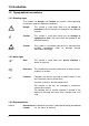
1 Introduction 1.2 Typographical conventions 1.2.1 Warning signs The symbols for Danger and Caution are used in these operating instructions under the following conditions: V * E Danger This symbol is used when there may be danger to personnel if the instructions are ignored or not followed correctly. Caution This symbol is used when there may be damage to equipment or data if the instructions are ignored or not followed correctly.
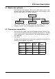
2 Protocol description 2.1 Master-slave principle The communication between a PC (master) and a device (slave) using MODbus takes place according to the master-slave principle, in the form of a data request/instruction - response. Master Slave 1 Slave 2 Slave n The master controls the data exchange, the slaves only have a response function. They are identified by their device address. 2.2 Transmission mode (RTU) The transmission mode used is the RTU mode (Remote Terminal Unit).
2 Protocol description 2.3 Device address The device address of the slave can be set between 0 and 254. Address 0 is reserved. H A maximum of 31 slaves can be addressed via the RS422/ 485 interface. Two forms of data exchange can be distinguished: Query Data request/instruction by the master to a slave via the corresponding device address. The slave addressed responds. Broadcast Instruction by the master to all slaves, via the device address 0. The connected slaves do not respond.
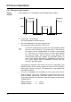
2 Protocol description Timing Data request from master transmission time = n characters * 1000 * x bits/(baud rate) Marker for end of data request 3 characters * 1000 * x bits/(baud rate) Processing of the data request by the slave (max.
2 Protocol description 2.4.1 Timing of a data request Timing scheme A data request runs according to the following timing scheme: Master Master Data request Datenanfrage Data request Datenanfrage Response Antwort Slave Slave t t0 t1 t0 t0 End marker = 3 characters (the time depends on the baud rate) t1 This time depends on the internal processing. The maximum processing time is 250 msec. H t2 A minimum response time can be set in the controller, under the menu item “Interface”.
2 Protocol description 2.4.2 Communication during the internal processing time of the slave No data requests from the master are permitted during the internal processing time. Any data requests that are made during this period will be ignored by the slave. 2.4.3 Communication during the response time of the slave No data requests from the master are permitted during the response time of the slave.
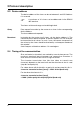
2 Protocol description Response in the event of an error Slave address Function 1 byte 1 byte Error code Checksum CRC16 1 byte 2 bytes XX OR 80h The function code is ORed with 0x80, which means that the MSB (most significant bit) is set to 1.
2 Protocol description 2.7 Checksum (CRC16) The checksum (CRC16) serves to recognize transmission errors. If an error is identified during evaluation, the corresponding device does not respond.
2 Protocol description 2.8 Interface 2.8.1 Configuration The plast series of controllers have expanded settings, which are marked.
2 Protocol description Check h Press the P + I keys “ON” for an active termination resistor, or “OFF” for an inactive termination resistor, will be shown to the right of the green “VErS” display. 2.8.3 Current-loop interface (only for the plast series ) The "Current-loop interface" option in this controller can interrupt the current flowing in the loop (transmitting) or “listen in” to the switching events in the current loop (receiving).
2 Protocol description 16
3 Functions The following functions are available for the device: Function number Function 0x03 or 0x04 Read n words 0x06 Write one word 0x10 Write n words 3.1 Read n words This function reads n (n≤32) words, starting from a defined address. Data request Response Example Slave address Function Address Word number (max.
3 Functions 3.2 Write one word For the “write word” function, the data blocks for instruction and response are identical.
3 Functions 3.3 Write n words This function writes n (n≤32) words, starting from a defined address. Instruction Response Example Slave address Function 0x10 Address Word of first word number (max.
3 Functions 20
4 Data flow H The RS422/485 interface is inactive during communication via the setup interface. All process values (variables) together with their addresses, data type and access mode are described below. References are as follows: R/O read access only R/W read and write access char, byte byte (8 bits) Byte sequence int integer (16 bits) Bit x bit No.
4 Data flow Example: Transmission of the floating-point number 3000 PC (master): 00 80 3B 45 MODbus: 80 00 45 3B Byte 1 2 3 4 Long values Example: Transmitting the number 66051 22 PC (master): 03 02 01 00 MODbus: 00 01 02 03 Byte 1 2 3 4
5 Address tables 5.
5 Address tables Address 0x0026 0x0027 0x0028 0x002A 0x0030 0x0034 0x0035 0x0037 0x003D 0x003F 0x0041 0x0043 0x0045 0x0047 0x0049 0x004B 0x004D 0x004F 0x0053 0x0054 0x0055 0x0056 0x0057 0x0058 0x0059 24 Data type/ bit number Bit 3 INT Bit 0 Bit 1 Bit 2 Bit 3 Bit 4 Bit 5 Bit 8 Bit 9 Bit 10 Bit 11 Bit 12 Bit 13 INT Bit 0 ...
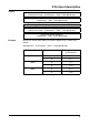
5 Address tables Address 0x005B 0x005D 0x0061 0x0063 0x0067 0x0069 0x006B 0x006D Data type/ bit number LONG LONG LONG LONG LONG LONG LONG LONG Access Signal designation R/O R/O R/O R/O R/O R/O R/O R/O Program run time (in seconds) Residual program time (in seconds) Segment run time Residual segment time Timer run time, timer 1 Timer run time, timer 2 Timer run time, timer 3 Timer run time, timer 4 Access Signal designation R/W R/W R/W R/W Setpoint W1 Setpoint W2 Setpoint W3 Setpoint W4 5.
5 Address tables Address 0x300E 0x3010 0x3011 0x3012 0x3013 0x3014 0x3016 0x3018 0x3019 0x301A 0x301C 0x301E 0x3020 0x3022 0x3024 0x3025 0x3026 0x3027 A Data type/ bit number FLOAT INT INT INT INT FLOAT FLOAT INT INT FLOAT FLOAT FLOAT FLOAT FLOAT INT INT INT INT Access Signal designation R/W R/W R/W R/W R/W R/W R/W R/W R/W R/W R/W R/W R/W R/W R/W R/W R/W R/W Parameter set 1: HyS2 Parameter set 1: tt Parameter set 1: y0 Parameter set 1: y1 Parameter set 1: y2 Parameter set 2: Pb1 Parameter set 2: Pb2 P
5 Address tables Address 0x0088 0x0089 0x008B 0x008D 0x008E 0x008F 0x00B9 0x00BA A Data type/ bit number INT FLOAT FLOAT INT INT FLOAT INT INT Access Signal designation R/W R/W R/W R/W R/W R/W R/W R/W Limit comparator 3, switch-off delay Limit comparator 4, limit AL Limit comparator 4, switching differential Limit comparator 4, switch-on delay Limit comparator 4, switch-off delay Ramp function, slope Alarm text (1-2) Alarm text (3-4) Write operations to these parameters result in them being saved to
5 Address tables Address 0x00B5 0x00B6 0x00B7 0x00B8 A Data type/ bit number INT INT INT INT Access Signal designation R/W R/W R/W R/W Control contacts, segment 5 Control contacts, segment 6 Control contacts, segment 7 Control contacts, segment 8 Write operations to these parameters result in them being saved to the EEPROM. These memory chips only have a limited amount of write cycles (about 10000), this is why this function can be switched off in the case of frequent programming.
5 Address tables Address Access Signal designation 0x0073 Data type/ bit number INT R/W 0x0074 INT R/W 0x3200 0x3202 0x3004 0x3006 0x3008 FLOAT FLOAT FLOAT FLOAT INT Bit 0 Bit 1 Bit 7 W/O W/O W/O W/O W/O W/O W/O W/O Setpoint switching (0=off) 1 — 4=W1 — W4 Parameter set switching (0=off) 1=P1 2=P2 Setpoint Process value Math 1 Math 2 Logic 1+2 Logic 1 (=0x0081) Logic 2 (=0x0082 Activation (=0x0080) 5.
5 Address tables 30
JUMO GmbH & Co. KG JUMO Instrument Co. Ltd. JUMO Process Control, Inc. Street address: Moltkestraße 13 - 31 36039 Fulda, Germany Delivery address: Mackenrodtstraße 14 36039 Fulda, Germany Postal address: 36035 Fulda, Germany Phone: +49 661 6003-0 Fax: +49 661 6003-607 e-mail: mail@jumo.net Internet: www.jumo.net JUMO House Temple Bank, Riverway Harlow, Essex CM20 2TT, UK Phone: +44 1279 635533 Fax: +44 1279 635262 e-mail: sales@jumo.co.uk Internet: www.jumo.co.