
Datasheet


V2.00/EN/00710338/2019-11-07
Page 18/24Data Sheet 706521
-802*PE+&R.*
'HOLYHU\DGGUHVV 0DFNHQURGWVWUDH
)XOGD*HUPDQ\
3RVWDODGGUHVV
)XOGD*HUPDQ\
3KRQH
)D[
(PDLO PDLO#MXPRQHW
,QWHUQHW ZZZMXPRQHW
-802,QVWUXPHQW&R/WG
-802+RXVH
7HPSOH%DQN5LYHUZD\
+DUORZ(VVH[&0'<8.
3KRQH
)D[
(PDLO VDOHV#MXPRFRXN
,QWHUQHW ZZZMXPRFRXN
-8023URFHVV&RQWURO,QF
0\HUV5RDG
(DVW6\UDFXVH1<86$
3KRQH
)D[
(PDLO LQIRXV#MXPRQHW
,QWHUQHW ZZZMXPRXVDFRP
70652100T10Z001K000
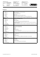
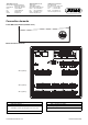
Connection diagram
The connection diagram in the data sheet provides preliminary information about the connection options. For the electrical connection, only use
the quick start guide or the operating manual. The knowledge and the correct technical execution with the safety information and warnings con-
tained in these documents are mandatory for mounting, electrical connection, and startup as well as for safety during operation.
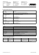
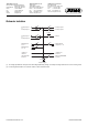
Analog inputs
Measuring probe Terminals and connection symbol Connection element.terminal /
assignment
Thermocouple Analog/digital option
(order code 1):
7.1-5 / Analog input 1
8.1-5 / Analog input 2
9.1-5 / Analog input 3
11.1-5 / Analog input 4
12.1-5 / Analog input 5
13.1-5 / Analog input 6
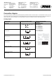
RTD temperature probe
Two-wire circuit
RTD temperature probe
Three-wire circuit
RTD temperature probe
Four-wire circuit
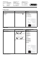
Resistance transmitter
Resistance/potentiometer
Two-wire circuit
12345
12345
12345
12345
12345
ES
A
12345