es Paperless Recorder for secure acquisition of FDA-compliant measurement data B 70.6560.4 Installation Instructions 11.
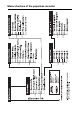
Menu structure of the paperless recorder
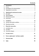
Contents 1 Introduction 5 1.1 Preface .......................................................................................................... 5 1.2 Arrangement of the documentation ........................................................... 6 1.3 Typographical conventions ......................................................................... 8 2 Identifying the instrument version 2.1 Nameplate .................................................................................................
Contents
1 Introduction 1.1 Preface B Please read these Installation Instructions before commissioning the instrument. Keep the instructions in a place that is accessible to all users at all times. Please assist us to improve these installation instructions, where necessary. Your suggestions will be appreciated.
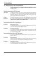
1 Introduction 1.2 Arrangement of the documentation The documentation for this instrument is addressed to the equipment manufacturer (OEM) and users with appropriate technical expertise. It consists of the following parts: Sales documentation in PDF file format White Paper The White Paper presents the company’s position with regard to the legislation “21 CFR Part 11” of the American health authority FDA (Food and Drug Administration).
1 Introduction B 70.6560.2.0 Interface description (serial interfaces) This provides information on the communication (RS232; RS422/RS485) with supervisory systems. Interface description (Ethernet interface) This provides information on the connection of a paperless recorder to a company-internal network. The description is incorporated in the B 70.6560.2.0 B 70.6560.2.
1 Introduction 1.
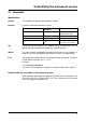
2 Identifying the instrument version 2.1 Nameplate Identification Position The nameplate is affixed to the paperless recorder. Contents It contains important information such as: Description Instrument type Sales number Production number Supply voltage Designation on nameplate Typ VARTN F-Nr Example 706560/10-888,000-510032-0032-23,020 70/00342163 0022969000003130006 AC 110 … 240V +10/-15%, 48…63Hz Typ Please compare the type that was supplied with your order details.
2 Identifying the instrument version 2.2 Type designation Paperless recorder for secure acquisition of FDA-compliant meas. data (1) Basic version 706560/00 paperless recorder, no analog inputs 706560/01 paperless recorder, no analog inputs, incl. PC software package and interface cable/adapter 706560/10 paperless recorder with 6 analog inputs 706560/20 paperless recorder with 6 analog inputs, incl.
2 Identifying the instrument version 2.3 Standard accessories - 1 Installation Instructions B 70.6560.4 - 1 Operating Instructions B 70.6560.1 - 2 mounting brackets - 4 cable-tie with foot (can be released) for strain relief of the sensor connection cables - 1 CD with additional documentation (see Chapter 1.2 “Arrangement of the documentation”) 2.
2 Identifying the instrument version 12
3 Installation 3.1 Location and climatic conditions The location should be as free as possible from shock and vibration. Stray electromagnetic fields from motors, transformers etc. should be avoided. The ambient temperature at the location can be 0 to +45°C, at a relative humidity of ≤75%, no condensation. v Chapter 4.1 “Installation notes” 3.
3 Installation Fitting into the panel min. 200 Panel Fitting in position h Insert the paperless recorder from the front into the panel cut-out. h From the back of the panel, hook the two mounting brackets into the recesses on the sides of the housing. The flat sides of the brackets must be against the housing. h Place the mounting brackets against the rear of the panel and tighten them evenly.
4 Electrical connection 4.1 Installation notes k The choice of the cable, the installation and the electrical connection must conform to the requirements of VDE 0100 “Regulations on the Installation of Power Circuits with nominal voltages below 1000V”, or the appropriate local regulations. k Work inside the instrument must only be carried out to the extent described and, like the electrical connection, only by qualified personnel.
4 Electrical connection 4.2 Procedure h Carry out electrical connection as per Chapter 4.3 “Connection diagram”. h Screw back panel cover on (spacer bolt first) h If necessary, use cable-ties for strain relief of connecting cables.
4 Electrical connection 4.3 Connection diagram V Back panel The electrical connection must only be carried out by qualified personnel.
4 Electrical connection Terminal assignment Connector Connection diagram Supply Supply voltage as per data sheet L1(L+) N (L-) PE Analog inputs Thermocouple 1 to 12 Resistance thermometer in 2-wire circuit 1 to 12 1 2 3 4 RL RA=RL RA Resistance thermometer in 3-wire circuit 1 to 12 1 2 1 to 12 1 2 5 3 4 5 3 4 5 3 4 5 Resistance thermometer in 4-wire circuit Resistance transmitter 1 to 12 Potentiometer in 2-wire circuit 1 to 12 1 2 RL RA=RL RA Interfaces Pot
4 Electrical connection Interfaces Terminal assignment Connector Connection diagram RS422 9-pole SUB-D socket (extra code) 20 3 4 5 8 9 TxD+ transmit data + RxD+ receive data + GND ground TxD- transmit data RxD- receive data - RS485 9-pole SUB-D socket (extra code) 1 2 3 6 6 7 8 9 1 2 3 4 5 6 7 8 9 1 2 3 4 5 6 7 8 9 21 3 RxD/TxD-P B-cable receive/transmit data-Plus 5 DGND data transmission potential 6 VP supply voltage-Plus 8 RxD/TxD-N A-cable receive/transmit data-N Ethernet RJ45 socket (ext
4 Electrical connection Digital I/O Terminal assignment Connector Connection diagram Open-collector output (25V max., 100mA max.
5 Function check When the paperless recorder is installed and connected, it can be started up. After the supply voltage has been connected or switched on, the start screen will appear briefly. Start screen After the end of the initialization phase, the visualization level is automatically started. Visualization level The recorder is now in recording mode. Further steps A The instrument can be configured by an authorized person, either from the instrument keys or by using the setup program.
5 Function check 22
6 Device replacement / software update If you need to replace the device or update the software, this chapter will help you back up and restore all necessary settings and parameters. h Fill in this page before replacing the device.
6 Device replacement / software update Info Notes 24 After uploading the user list, the users must log in with the password that was initially assigned by the administrator. If a user no longer knows the password, then the user status has to be set to “New” and a new password assigned through the PCS software. After altering the device software (update), the process data are stored in a new PCA3000 archive.
7 Technical data Analog inputs (channels 1 — 12) Thermocouple Designation Type Standard Range Linearization accuracy1 Fe-Con L Fe-Con J Cu-Con U Cu-Con T NiCr-Ni K NiCr-Con E NiCrSi-NiSi N Pt10Rh-Pt S Pt13Rh-Pt R Pt30Rh-Pt6Rh B Chromel-Copel -200 -210 -200 -270 -270 -270 -270 -50 -50 0 -200 ±0.1% ±0.1% above -100°C ±0.1% above -150°C ±0.15% above -150°C ±0.1% above -80°C ±0.1% above -80°C ±0.1% above -80°C ±0.15% above 0°C ±0.15% above 0°C ±0.15% above 400°C ±0.
7 Technical data Designation Standard Cu 50 Connection Range Linearization accuracy Measuring current 2/3-wire 2/3-wire 4-wire 4-wire -50 to +100°C -50 to +200°C -50 to +100°C -50 to +200°C ±0.5°C ±0.9°C ±0.5°C ±0.6°C 500μA 250μA 500μA 250μA Connection type 2-, 3- or 4-wire circuit Shortest span 15°C max. 30 Ω per core for 3-/4-wire circuit max. 10Ω per core for 2-wire circuit Sensor lead resistance Range start/end freely programmable within the limits in 0.
7 Technical data Range start/end freely programmable within the limits in 0.1 mA steps Sampling cycle 6 or 12 channels 125msec Input filter Feature 2nd order digital filter; filter constant adjustable from 0 to 10.
7 Technical data Electrical data Supply (switch-mode power supply) Electrical safety Test voltages (type test) - mains supply circuit to measuring circuit - mains supply circuit to housing (protective conductor) - measuring circuits to measuring circuit and housing - electrical isolation between the analog inputs Supply voltage error Power consumption Electrical connection 110 — 240V AC +10/-15%, 48 — 63Hz or 20 — 30V AC/DC, 48 — 63Hz to EN 61 010, Part 1 of August 2002 overvoltage category II, pollution d
8 Index A Accessories 11 Analog inputs 18 B Back panel 17 C Climatic conditions 13 Commissioning 5 Connection diagram 17 Cover for back panel 17 D Digital I/O 20 Documentation, arrangement of 6 E Electrical connection 15 Electrostatic discharge (ESD) 5 F Fitting into the panel 14 Function check 21 I Identification of namplate 9 Installation 13 Installation notes 15 Instrument documentation in PDF file format 6 Instrument documentation in printed form 6 Instrument version, identification of 9 Interface
8 Index N Nameplate 9 Note signs 8 O Outline drawings 13 P PROFIBUS-DP 10, 19 R Rear view 17 Relay outputs 19 Repeat order for recorder in the identical version 9 Returning 5 S Sales documentation in printed form 6 Standard accessories 11 Start screen 21 Supply 18 T Technical data 25 Type designation 10 Typographical conventions 8 V Visualization level 21 W Warning signs 8 Warranty 5 30
JUMO GmbH & Co. KG JUMO Instrument Co. Ltd. JUMO Process Control, Inc. Street address: Moltkestraße 13 - 31 36039 Fulda, Germany Delivery address: Mackenrodtstraße 14 36039 Fulda, Germany Postal address: 36035 Fulda, Germany Phone: +49 661 6003-0 Fax: +49 661 6003-607 e-mail: mail@jumo.net Internet: www.jumo.net JUMO House Temple Bank, Riverway Harlow, Essex CM20 2TT, UK Phone: +44 1279 635533 Fax: +44 1279 635262 e-mail: sales@jumo.co.uk Internet: www.jumo.co.