JUMO PCC PCA Communication Software B 70.9702.
Contents 1 Introduction ...................................................................................... 5 1.1 Preface ................................................................................................................ 5 1.2 Typographical Conventions ............................................................................... 5 1.3 Documentation for PC Software Components ................................................ 6 2 PCA Communication Software ..........................
Contents 8.1.4 8.1.5 8.1.6 8.1.7 Output orders ..................................................................................................... Default Settings .................................................................................................. List Settings ........................................................................................................ Exit ......................................................................................................................
1 Introduction 1.1 Preface Warranty Data backup 1.2 H A If any difficulties should arise during start-up, please do not manipulate the unit in any way. Doing so may jeopardize your warranty claims. Please contact the nearest subsidiary or the head office in such a case. Make a regular backup of your configuration file.
1 Introduction 1.3 Documentation for PC Software Components B 70.9701.0 PC Evaluation software (PCA3000) PCA3000 serves to visualize and evaluate process data (measurement data, batch data, messages, device audit trails, etc.). Process data can be read in via the CompactFlash memory card or made available through the PCC software. B 70.9702.0 PCA Communication software (PCC) PCC is responsible for the data transfer from a device (e.g. paperless recorder) to a PC, or within a network. B 70.9703.
2 PCA Communication Software 2.1 Purpose The PCA Communication Software PCC is used for connecting a PC to a paperless recorder or a controller with recording function in order to transfer registration data from the device to the PC. Depending on the device and the PC, different interfaces are available for data transfer, e. g. serial interface, USB, Ethernet. Data recorded in the device can be readout manually or automatically (timecontrolled), even from several devices at the same time.
2 PCA Communication Software Communication In addition, the following are required for communication between the PC and device: - PC interface cable including adapter (only when using the Setup interface) or - Serial interface cable (when using the RS232C or RS422/485 interface) or - USB cable (when using the USB port) - Network connection (when using the Ethernet connection). 2.
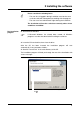
3 Installing the software A Please consider the folowing items: - The user who is logged in during installation must be the same as the one who will subsequently be working with the program. - The user must have administrator rights during the installation. The installation will not be carried out correctly unless these conditions are fulfilled.
3 Installing the software h Now enter the required license numbers. No 30-day test version is available for installation with an enhanced security level. h Define the program folder into which the icons for starting the software will be copied. H The next two steps only need to be performed for an installation with an enhanced security level. h Enter the installation options. h Enter the path for user lists. Further information is available in the Operating Manual "PC Security Manager Software.
3 Installing the software Starting the Installation h Now click H to install the selected software components. With an enhanced security level, you will have the opportunity of starting the PC Security Manager software directly when the installation is finished ( ). h Finish the installation by clicking H . “Devices with an enhanced security level” can only be operated with the PCC software described here.
3 Installing the software 12
4 Operation 4.1 Starting the Program h Call up the program from the start menu The start screen appears, with information about the installed version. Logging in to the program Logging in when starting the program depends on the type of installation. - If software for a device with an enhanced security level has already been installed on the relevant PC, there is always a password prompt. - Normally (without enhanced security level) log-in only occurs when it has been activated by the user.
4 Operation Password entry h Log in to the program. Select your name (user ID) and enter the password. h Click . When you log in for the first time, the password that has been defined may have to be altered. A request to alter the password will also be made when your password has expired. When creating the user list, the administrator decides whether a password can expire (only available with an enhanced security level). Password alteration h Enter the previous (old) password.
4 Operation Start automatic mode after waiting time This window appears if the option "Activate automatic mode after starting program" has been selected in the device list. v Chapter 5.1 "Editing the Device List" By clicking on button you can inhibit the start of automatic mode. Thus you have the oportunity to change the settings of automatic devices before starting automatic mode manually. With button you can start automatic mode immediately, i. e. before waiting time has expired.
4 Operation 4.2 Windows of the User Interface Navigation tree A tree structure showing all connected devices Output orders window Point in time and number of output orders per device Active devices window A list of all the devices that are active (in PCC) at present, e.g. retrieving data Dialog window The settings for the connected devices are listed here. The mouse can be used to adjust the window to the required size. The windows for active devices and output orders can be shown or hidden.
4 Operation 4.3 Device types Devices with or without CompactFlash memory card or USB host interface H The operating instructions below make frequent reference to “Device type” 1 or 2 or to “Devices of type” 1 or 2. Device type 1 Device type 1 designates devices that have no slot for CompactFlash memory cards and no USB host interface. These are, for example, LOGOSCREEN, LOGOSCREEN 500, IMAGO 500 or IMAGO F3000.
4 Operation 4.4 Rights As described in “Logging in to the program” on page 13, a user must log in with the correct ID and password under some circumstances when the program is started. As a result of this, log-in rights are assigned to individual functions. Therefore it may not be possible to activate all functions, depending on the user or type of installation.
4 Operation 4.5 Navigation tree The settings for the device list are made in the navigation tree, where the individual devices (from which the data are to be read out) are entered. Fold up tree ( ) and unfold tree ( ). Use the mouse to change the settings in the device list or to add a device to the list.
4 Operation 4.6 Dialog window The currently valid entries are shown in the dialog window. The dialogs for altering the settings can also be called up in the dialog window. Click on the arrows (by using the left mouse button when the mouse pointer is positioned on an arrow) to open (unfold) and close (fold up) the current parameter values. Unfold / Fold up Device list Use the right mouse button, or double-click the device list to change the global settings. v Chapter 5.
4 Operation Device type (device) Right click or double click a device to change all the settings for the device. If the function “Use the Assistant for device settings” is active, then all the settings will be requested, one after another. If the Assistant is not active, you will have to call up the various settings dialogs by hand. v Chapter 5.2 "Adding devices" v Chapter 8.2.
4 Operation 22
5 Device Management 5.1 Editing the Device List h Position the mouse pointer on “Device list” and press the right mouse button. A new device is entered in the list here. Alter the global settings for the device list. Global settings h Select function Edit device list. Descriptive text. This appears in the dialog window and is also printed out. Default directory for archive data that has Settings for e-mail messaging.
5 Device Management E-mail settings Settings for e-mail messaging. Selection of different possibilities for (optionally) logging into the e-mail server User name and password for logging in on the e-mail server After you click the button, you can make settings for the SMTP and if applicable the POP3 server. Information about the sender, used in the e-mail Regardless of the daily status A status message is sent message, an e-mail is sent daily by e-mail at this time when an error occurs.
5 Device Management Server settings Settings for SMTP server or POP3 server. IP address or host name of the SMTP or POP3 server. When the host name is entered, the IP address can be determined by clicking "Convert host name to IP address“ (for information or to check whether the host name can be converted into an IP address). H 5.2 Port number or port name for the SMTP or POP3 service. The port name is replaced while the connection is being set up by the predefined port number (SMTP = 25; POP3 = 110).
5 Device Management Select device The following dialog appears if the setting "Use the Assistant for device settings" is active. Select device type and version. Select device group / machine line to which the device shall be assigned to. (This drop-down-menu is only visible if there are at least two device lists.) Selection of connection presettings (device-dependent) If the option is active ( ), a check is made at the end, whether the chosen device can be accessed via the selected interface.
5 Device Management Logging in on the device Logging in to the device is only required for devices with internal user administration (e.g. LOGOSCREEN cf). Save ID and password Do not log in Do not log in The default setting of the software is that a user who is logged in is automatically logged in to a device that is found with the user’s name and password, and can thus communicate with this device. Set option ( ) if you do not want to log in.
5 Device Management PC Communication interface Available options are: 28 USB Setup interface USB USB RS232 RS232 RS232 RS232 to RS422/485 converter RS232 Setup interface Modem Modem - RS232 Modem Modem - RS422/485
5 Device Management TCP-IP (Intranet / Internet) Ethernet TCP-IP (Intranet / Internet) TCP-IP to RS232/RS485 converter type: I-7188E series TCP-IP (Intranet / Internet) TCP-IP Ethernet to RS232/RS485 converter type: W&T Com server The next steps depend on the interface or type of connection that has been selected. USB-TTL converter USB interface The following parameters must be selected: Connected TTL converters Select converter If multiple converters are connected, a selection can be made here.
5 Device Management Serial interface CPU Activate check yes/no If check is active, the device will only be connected if the CPU number matches. Path Activate check yes/no If check is active, the device will only be connected if the USB path matches. The following parameters must be selected. Connected to COM1, COM2 The PC interface to which the device is connected. Transfer rate 9600, 19200, 38400 The transfer rate must match the one that has been set in the device.
5 Device Management Analog modem / ISDN TCP/IP PORT The following parameters must be selected. Telephone number Enter the telephone number for the required device. Connect via Select the modem that will be used to make the connection. Communication protocol Modbus protocol The Modbus protocol must be set here. Device address 1 … 254 Device address for the Modbus protocol. The following parameters must be selected. IP address / HOST name xxx.xxx.xxx.xxx Specify the IP address (Example: 192.168.
5 Device Management TCP/IP PORT (ICPDAS 7188E1-8) The following parameters must be selected. IP address / HOST name xxx.xxx.xxx.xxx Specify the IP address (Example: 192.168.0.10) or the host name of your device. (If the host name is used, the IP address can be determined for verification by clicking "Convert host name to IP address".) Serial port COM1, COM2, ... Serial port of the converter to which the device is connected.
5 Device Management Control signal RS232 If the RS232 interface on the device is used. RS232 setup interface (TTL) If the setup interface on the device is used. RS422-RTS If the RS422/485 interface on the device is used. RS422-DTR RS485-RTS RS485-DTR RS232/RS485 adapter cable Recommendation: Use a Spectra converter with an automatic transmit/ receive changeover. Only for internal test purposes.
5 Device Management Time settings h After you click the automatic read-out. button, you can enter the times for the Click OK when the times have been set.
5 Device Management Archive h After you click the button, you can alter the settings for the archive (file name and directory). When the archive settings are complete, click OK.
5 Device Management You will then get a summary for the new device. h Click to finish adding a new device. The device should now be set up and ready for reading out data. If you want the device to read out data automatically, automatic mode must be started. It can be started through menu function Automatic ➔ Automatic mode.
5 Device Management 5.3 Changing the settings h Position the mouse pointer on the icon and press the left mouse button. The tree in the navigation window unfolds. h Position the mouse pointer on the parameter group you want to change, and right click. h Select “... Edit.” The corresponding dialog for making changes opens, depending on the selected parameter group.
5 Device Management In this example, the "Time settings" dialog appears. v Chapter 6 "Time Settings" v Chapter 8.2.3 "Editing" 5.4 Device list sorting You can sort the device by moving devices within their device type. It is also possible to move device types within the device list. To sort the device list, follow these steps: h Mark the device type or device with the mouse pointer.
5 Device Management 5.5 Creating additional device lists The default device list is named “device list“. This name can be changed. In addition further device lists can be created and their names can freely be chosen. v Chapter 8.2.4 "Device groups/Machine lines" Using several device lists has the advantage that devices can be grouped together or assigned to machine lines. Each device list is displayed in a separate window. The following example shows two device lists named „Oven“ and „Boiler“. 5.
5 Device Management With assistant Enter IP address (or host name) of device Enter port number of PROXY server Enter IP address (or name) of PROXY server Changing the extended settings You can change connection properties for entering IP address and port number of the PROXY server as follows: h Click on Features within Connection window. In the next window click on Expanded... The following window is opened: h Select „HW:Connect via a PROXY“, set the new value to 1 and finish the dialog with OK.
6 Time Settings In the “Time settings” dialog, you can set the cycle types for retrieving data, synchronizing clocks, operating times for each day of the week, and the settings for the response to an error. Here you can also make settings to define how data is read out and evaluated. The menu for setting the times for retrieving data can be accessed - when a new device is set up or - by means of the menu function Edit ➔ ... Times: - Edit.
6 Time Settings A I It depends on the specific device whether, when using an Ethernet connection via TCP/IP, only one program from the PC software components can operate through the interface. If only one program can operate, other programs can still continue to communicate with other devices. Example: PCC is used to access a paperless recorder (Device 1) via TCP/IP. PCS (Security Manager) can be used to access a different paperless recorder (Device 2) via TCP/IP.
6 Time Settings H Example 1 If the period is set to less than 60 seconds, the data are read out in a continuous cycle, i.e. the connection to the device is never broken. A continuous cycle is only stopped if an error occurs, on cancellation by the user, or at the end of the operating period (if it is active and the read-out has been carried out 100%). The parameter for “Continue read-out beyond the operating period” in the “Advanced (1)” tab also has an effect on the end of the operating period.
6 Time Settings Start time for next read-out of data No change If a change is made to the time settings, the new time will only take effect after the next read-out. Example: Read out will be performed Mondays at 8:00 AM. It is currently 7:00 AM Monday. You set “Retrieve at” to 10:00 AM and leave the “Calculation of start date” set to “No change.” The next read-out happens at 08:00 AM. Then the new setting will be made for 10:00 on Monday of the following week.
6 Time Settings Time synchronization The setting for when the device time will be synchronized to the PC time. This is used to eliminate differences between the PC and the device. H It is only possible for devices that support time synchronization. H Synchronization can only be performed during operating periods. Setting that determines whether and how the start date/ time is calculated Cyclic check This defines a check for whether the attached device is still connected to the PC.
6 Time Settings Operating periods Here you can set the periods of time for which the device is accessible, i.e. the system is in operation. These settings are used to calculate the start dates/ times for activities (e.g. retrieving or reading out data, time synchronization, and cyclic checks) and in this way also reserve specific time periods for other programs. Weekdays on which the device will be operational The time of day from ... to ...
6 Time Settings Time schedule These settings are intended for use when data must be retrieved or read out at individually specified times that cannot be set to occur periodically. A These times must lie within the operating periods, and the action (retrieving/reading) must be set to schedule! After the processing of a scheduled event, it will be removed from the list by the software. List for the special time entries Time and date entry.
6 Time Settings Expanded (1) A This function depends on the device version! Inactive ( ): All data will be read out from the device. For Type 1 devices (e.g. IMAGO 500) it can happen that a memory alarm is generated during the read-out. After a successful read-out, the alarm will automatically be reset. Active ( ): Only new data will be read, even if “old” data is still missing in the archive.
6 Time Settings Expanded (2) Active ( ): The scheduled times are calculated from the next valid point, as if the PCC software had just made a read-out. Inactive ( ): Data that have not yet been read out (from devices where the scheduled time has passed) is read immediately and then the scheduled times are recalculated (see register for operating periods).
6 Time Settings 50
7 Archive The menu for setting the archives for retrieved data can be accessed - when a new device is set up or - by means of the menu function Edit ➔ Edit archive. In the latter case, the “Archive” field must be selected in the navigation tree. After calling up this function, the default archives that have been set will appear, and the other functions will be grayed out (not selectable). A new archive can only be set if the tick mark is removed by clicking.
7 Archive Current default archive (directory) v Chapter 8.1.5 "Default Settings" Click (with the left mouse button) to start the PCA3000 software and bring up the archive data in the display. If there are several archive files in the directory for a device, then the first archive that is found will be used. Archives for automatically read data Archives for manually read data Changing archive automatically v Page 54 Using an output form v Page 54 Active ( ): Data is immediately accepted for evaluation.
7 Archive If the standard archive paths (or archives) shall not be used, the concerning function has to be deactivated ( ). Example: Inactive: Archives for automatically read data will not be used for manually read data. Inactive: The default archive path for manual read-out will not be used. Double clicking on it allows you to enter the name directly. Add another archive for manually read data. Edit archive entry for manually read data. Remove an archive from the list.
7 Archive Changing archive When the set time range is exceeded, a new archive is automatically created. The following settings are possible: - inactive - 1 day - 1 week - 1 month - 1 year H Output form 54 The time range refers to the time stamps in the data of the device. It does not refer to the points in time when data are read or fetched from the device. Therefore an archive change is not possible until device data with a corresponding time stamp are available.
8 Menu Functions and Toolbar 8.1 File 8.1.1 Export as RTF Text This function exports the information in the dialog window as an RTF text in the file to be selected. 8.1.2 Print, Print Preview This function prints all the connection data for the devices marked in the diagram in the dialog window.
8 Menu Functions and Toolbar Print preview 8.1.3 Printer Setup This switches to the list of printers installed on the PC.
8 Menu Functions and Toolbar 8.1.4 Output orders When outputs have been stopped (tick mark visible), data are no longer output into output forms. Nevertheless, outputs will not be lost because they are entered on a list with output orders. In this case, after manual read out, the automatic start of PC Evalution software PCA3000 is also deactivated (manual start by using button is possible). In the window for output oders every device is shown with time and number of outputs (e. g. batches): v Chapter 4.
8 Menu Functions and Toolbar 8.1.6 List Settings Right-click on the device list You can enter additional information on the list in this field. The default PCA3000 archive is used. - Do not set a tick if another archive directory is required. Device settings are made with the Assistant. Automatic mode is active after the program starts. Messaging via e-mail is activated. Click here to select a different archive (instead of the default archive for PCA3000) or to enter the name directly in the field.
8 Menu Functions and Toolbar 8.1.7 Exit This terminates the program immediately after any current activities, such as reading out data, have been completed. During the time that elapses until all activities have been completed, no new activities will be started. Activities of connected devices can also be cancelled. In this case, the program is immediately terminated. If any devices are still active after clicking out), then the following dialog will appear. Click the upper button (e.g.
8 Menu Functions and Toolbar 8.2 Editing The entry in the navigation tree defines which of the functions New, Edit, Duplicate, and Remove are available. Device list If the device list item is active, then the following functions are available. v Additional information can be found in Chapter 8.2.1 "Device List". Device type If a device type (e.g. LOGOSCREEN es/cf) is active, then the following functions are available. v Additional information can be found in Chapter 8.2.2 "Device Type".
8 Menu Functions and Toolbar 8.2.1 Device List Editing the device list Remove h Edit ➔ Device list: - Edit (or press the F4 function key) The entry marked in the tree structure will be edited. v Chapter 8.1.6 "List Settings" h Edit ➔ [Device]: - Remove (or press the “Del” key) This removes a connected device from the device list. h Click on “Yes” to remove the entry from the device list.
8 Menu Functions and Toolbar Move a device to another device list h Create a new device list if necessary v Chapter 8.2.4 "Device groups/Machine lines" h Mark the device in the navigation tree h Edit ➔ [Device]: - Edit (or press the F4 function key) h Select the required device list in field Device group / machine line h Finish dialog (OK or Forward... ; depending on dialog) The device is moved to the selected device list. 8.2.
8 Menu Functions and Toolbar 8.2.3 Editing Edit connection h Edit ➔ ... Connection: - Edit (or press the F4 function key) The “Return call” function is only available for specific device types with an active modem connection (e.g. for the IMAGO 500 controller). Here you must enter the number of the PC that will be called by the device. The log-in options have already been described on Page 27. If you click connection.
8 Menu Functions and Toolbar Edit Teleservice Edit ➔ ... Teleservice: - Edit (or press the F4 function key) The cycle time determines the interval for updating the display. The font size determines the size for display of the Teleservice window. Editing events h Edit ➔ ... Events: - Edit (or press the F4 function key) The “Events” list is designed for fast diagnostics and checking. Events that have been entered here can be deleted. However, deleting them has no effect on the Audit Trail entries.
8 Menu Functions and Toolbar Error indication The toolbar contains two bell icons for indicating errors. The green bell becomes active if a new error occurs in the device that is marked in the navigation tree. The red bell becomes active if a new error occurs for any device. If errors occur in more than one device, the bells remain active until you have looked at all the errors. H The number of different devices with new errors is limited. 8.2.
8 Menu Functions and Toolbar 8.3 Data Transfer 8.3.1 Reading out Raw Data (Manually) Depending on the device that is used, different information must be provided when manually reading out LOGOSCREEN 500cf/es/cf/nt raw data. For devices of type LOGOSCREEN 500 cf, LOGOSCREEN es, LOGOSCREEN cf and LOGOSCREEN nt (device type 2) you can set what data is required by the device. H The value for the memory alarm is not affected, i.e.
8 Menu Functions and Toolbar The archive is selected here. Active ( ): After reading out the data, the evaluation software PCA3000 will be started automatically (if outputs are not stopped). The first archive that is found will be opened, depending on the settings described under „Edit archive” on page 63. v Additional information about using the data selection dialog can be found in the PCA3000 Operating Manual (B 70.9701.0).
8 Menu Functions and Toolbar 8.3.2 Fetching Raw Data (Manually) When raw data is fetched manually , a check in the device determines what data is not yet in the set archive. This command transfers only the data that is missing to the archive. H The value for the memory alarm is reset and marked as “fetched”! For Type 1 devices, please note the Times ➔ Advanced (1) tab (Page 48). h Click the icon. The missing data will be transferred to the selected archive in the PC.
8 Menu Functions and Toolbar Cancel automatic mode If you are about to cancel the read-out of data in automatic mode, the following dialog window appears: The procedure that was cancelled will be resumed at the earliest after this time has elapsed. Automatic mode must remain switched on! Click to cancel the reading out of data immediately. Make sure that the data have been retrieved in good time, to avoid a loss of data. Select the period during which the device will remain inactive.
8 Menu Functions and Toolbar 8.3.4 Teleservice Teleservice is used to show current process data of attached devices. Teleservice can be active for several devices at the same time. The interval at which data is updated can be adjusted. The font size can also be changed. v „Edit Teleservice” on page 64 H H Exit Teleservice 70 To use Teleservice, "Modbus" or "Modbus TCP/IP" must be set as the connection protocol. Manual read-out or retrieval of data is not possible when Teleservice is active.
8 Menu Functions and Toolbar 8.4 Automatic The scheduled times and activities that have been set up under “Times” will only be automatically processed in automatic mode. 8.4.1 Starting/Stopping Automatic Mode You can tell whether automatic mode has been started by whether the icon appears depressed. If automatic mode has been stopped, the icon is shown as normal, i.e. not depressed Changeover started/ stopped .
8 Menu Functions and Toolbar 8.4.3 Stopping Active Devices This function terminates automatic mode (if it was active when the icon was clicked) and cancels all currently active data transmissions. Message for active automatic mode Cancel current transmissions Click the upper button for the lower ones to become active. Select "Stop all" to end the read-out immediately. If you select "All delayed", the read-out ends as soon as all currently active data blocks have been completely read.
8 Menu Functions and Toolbar 8.4.4 Start as service Starts PCC as a Windows system service. User name and password of the Windows user This function makes it possible to run PCC without the Windows user being logged in. In this manner, PCC starts as soon as the PC is turned on or restarted without a user having logged in.
8 Menu Functions and Toolbar 8.5 Tools 8.5.1 Enable Program Options You can use this function to enable additional software options, or to license a software that was installed as a demo version. h Tools ➔ Enable program options h Enter the license number and click “Registration” A After successful registration, the program must be closed and then restarted, so that the newly enabled options can be activated. No restart of Windows and no deinstallation is required! 8.5.
8 Menu Functions and Toolbar 8.5.3 Compressing the Device List This removes unused areas that have developed in the database (device list) – for instance, after deleting devices. If large gaps are present, compressing the device list will reduce the time taken to load and save it. 8.5.4 Resetting the Device List All the devices in the connection list will be deleted. None of the devices can be active (reading out/retrieving data, Teleservice), not even for a different program (Setup or PCS). 8.5.
8 Menu Functions and Toolbar 8.5.8 Synchronizing the Device Time This function is only available for devices that support synchronization (e.g. the paperless recorder LOGOSCREEN es/cf). Synchronization is only possible if the time difference between the PC and the device is not greater than 30 seconds. System requirements means that synchronization is only effective for differences >1 second. The residual error is <±1 second. After long periods of connected operation (e.g.
8 Menu Functions and Toolbar 8.5.10 Searching for a Device This function is used to search for connected devices on the interfaces that have been set up. H By pressing the Shift or Ctrl key and the left mouse button you can search through several interfaces for connected devices using one or several baud rates. Depending on the setting, the search procedure may take some time. The search covers the addresses 1 to 255 for the COM1 and COM2 ports.
8 Menu Functions and Toolbar 8.5.11 Preparing the Device Modem Recommended modems HSM 33.6 Analog industrial modem for mounting on DIN rails HSM ECO TA ISDN industrial modem for mounting on DIN rails TC35i GSM modem Part number: 00416612 Part number: 00416611 Part number: 00440255 Tixi HG GSM modem with alarm function for mounting on DIN rails Part number: 00487003 If other modems are used for the device, it may be necessary to alter the initialization string.
8 Menu Functions and Toolbar This function is used to prepare (initialize) a modem so that it can be connected as a device modem. h Connect modem to PC via a standard modem cable. Changeover between customized and original init strings Preparing the device modem Connection These settings must precisely match those in the device. The init (initialization) string for the connected modem is selected here. The init string is transferred to the connected modem.
8 Menu Functions and Toolbar use a different init string. After the software has been installed for the first time, the standard init strings (one string per modem) will be copied and treated as “customized” strings. In this way, any altered init strings will also be retained after a software update. This function means that the original strings can be attached to the “customized” ones, with the result that the modem list grows every time the function is called up.
8 Menu Functions and Toolbar 8.5.12 Renew Log-in / Alter Password This is a standard dialog that helps to protect all components of the PC software from unauthorized access. The software uses the log-in dialog for mandatory identification via the password. Cancellation or an incorrect password invalidates all the rights for the user. For security reasons, even ending the program is only possible after entering the correct password.
8 Menu Functions and Toolbar h Activate option “After log-in – alter password” and click . h Enter the password – the “Old password” field remains empty. When the entry has been concluded, click to activate the new password. From now on, the user name and the password will be requested when the program starts. H Initially, no start password is assigned to the “Maintenance” user either. When the program starts, log in with the “Maintenance” user name and enter a password as described above.
8 Menu Functions and Toolbar 8.5.13 Comment in Audit Trail This creates an entry in the PC audit trail (PCAT) for the better understanding of the activity that has been performed. v Chapter 1.3 "Documentation for PC Software Components" 8.5.14 Start Audit Trail This function starts the PC Audit Trail Manager software. 8.5.15 Set Audit Trail filter If the filter is set, only the entries of the corresponding device are displayed in the PC audit trail.
8 Menu Functions and Toolbar 8.6 View Update This updates the display on the screen. If devices are added to the device list, e.g. through the Setup software, while PCC is active, then this function adds the devices to the user interface of PCC. Deleted devices will only be removed when they are inactive, i.e. no data is being transferred. With numbers This inserts a unique ID number in front of every device name. This makes it easier to find a device if names are duplicated.
8 Menu Functions and Toolbar Filters The filter function can be use to filter out settings in the dialog window. Show hidden All hidden ements in the navigation tree are shown. This refers to empty device types and device lists, device types, and devices marked "Hidden." v Chapter 4.2 "Windows of the User Interface" Hide Device lists, device types, and devices can be marked "Hide." Then they will not appear in the navigation tree. Then can be shown with function "Show hidden." 8.
8 Menu Functions and Toolbar 8.8 Info Info via PCC Here you can obtain information on the version number of the program. Please have this number available if you have technical problems or queries and contact a service representative. Click button for additional information on any PC software components that may be installed. Please have these numbers available as well, if you have technical problems or queries and contact a service representative.
8 Menu Functions and Toolbar Supported devices List of device versions supported by the currently installed version of the PCC Communications Software. xx means that these positions will not be evaluated in the event of a version check (e.g. 172.01.05 is just as valid as 172.01.01 Automatic devices Shows all devices that have been configured for automatic mode (even if automatic mode is not activated).
8 Menu Functions and Toolbar 88
9 FAQs FAQ 1 Why can’t I see new devices that I created with the Setup software in the PCC software (which had already been started)? Answer Click on the menu function View ➔ Update – the PCC software will then accept the new devices. FAQ 2 What is the difference between “Retrieve raw data” and “Read out raw data”? Answer “Read out raw data ” does not affect the memory alarm of a device. On the other hand, “Retrieve raw data” does affect the memory alarm.
9 FAQs FAQ 5 How can I find the file with the measurement data, if the archive is only set as a directory, and no file name has been set? Answer The name is assigned automatically and is derived from the device identifier and a serial number. If there are one or more files with different names already containing data from the required devices, then the first file that is found will be used. A new file will not be created. Open the archive settings and click on PCA button ( ).
10 Index A Advanced time settings 48–49 Analog modem 31 Ansicht alles erweitern/komprimieren 84 Archive 35, 51 edit 63 for automatically read data 52 for manually read data 52 Assistant for device settings 23, 26, 58 Audit trail 6 comment 83 start 83 Audit-Trail Filter setzen 83 Ausgabe-Aufträge 57 Automatic 71 Automatic devices 87 Automatic mode 36, 58 exit 72 in background 71 start 71 stop 71 C Cancel 59 Automatic mode 69 manual read-out 69 Canceling the procedure 68 Changing archive 54 CompactFlash memo
10 Index Changing the settings 37 duplicate 61 Modem 78 New (with Assistant) 62 New (without Assistant) 62 remove 61 search 77 Synchronize time 76 Device list 20, 58, 60 additional lists 39 compress 75 edit 23, 61 Global settings 23 import 75 reset 75 save 75 sorting 38 Device selection 26 Device type 17, 21, 60, 62 Device Type 1 17 Device type 1 68 Device type 2 17, 68 Dialog window 16, 20 Duplicate 60 E Edit connection 63 Edit times 63 Editing 60, 63 Editing errors 64 Editing events 64 E-mail messaging 2
10 Index I ID 27 Identifier 26 Info about PCC 86 Installation program 9 Interface 28 Interface converter 80 IP address 25 ISDN 31 L Language 57 License number 74 List settings 58 Logging in on the device 27 Logging in when starting the program 13 M Modem preparation 79 Recommended modems 78 reset 80 N Navigation tree 16, 19 New 60 O Operating periods 46 Output form 54 P Parameter 21 Password 27 activate 81 alteration 14 change 82 entry 14 PC audit trail 83 PC communication 28 PCA3000 6 PCAT 6, 83 PCC 6
10 Index PCS 6 POP3 25 Port name 25 Port number 25 Print 55 Print preview 55–56 Printer setup 56 Program folder 86 Program options 74 Proxy server 39 Purpose of PCC software 7 R Reading out raw data (manually) 66 Registered license numbers 74, 86 Remove 60 Renew log-in 81 Reset error/event lists 75 Retrieving raw data (manually) 68 Rights 18 S Security level 18 Serial interface 30 Server settings 25 Service exit 73 remove 73 start 73 SMTP 25 Software documentation 86 Starting the program 13 Stopping activ
10 Index Tools 74 U USB interface 29 User ID 27 User interface 16 V View Filters 85 hide 85 Minimize/maximize all 84 Show hidden 85 update 84 With numbers 84 W Waiting time 15 Warranty 5 Window Active devices 85 active devices 16 Arrange icons 85 cascade 85 selection 85 tile horizontally 85 Windows system service 73 95
10 Index 96
JUMO GmbH & Co. KG Street address: Moritz-Juchheim-Straße 1 36039 Fulda, Germany Delivery address: Mackenrodtstraße 14 36039 Fulda, Germany Postal address: 36035 Fulda, Germany Phone: +49 661 6003-0 Fax: +49 661 6003-607 E-mail: mail@jumo.net Internet: www.jumo.net JUMO Instrument Co. Ltd. JUMO House Temple Bank, Riverway Harlow, Essex CM20 2DY, UK Phone: +44 1279 635533 Fax: +44 1279 635262 E-mail: sales@jumo.co.uk Internet: www.jumo.co.uk JUMO Process Control, Inc.