Operating instruction Radio Ref. no.: RAN ..514.. RAN ..914..
Table of contents 1. Safety notes................................................................................................... 3 2. Device overview ............................................................................................ 4 2.1.Operating elements........................................................................................ 4 3. Function......................................................................................................... 5 3.1.Intended use ..............
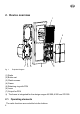
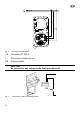
2. Device overview 1 2 7 6 fig. 1: 5 4 3 Exploded diagram (1) Radio (2) Button set (3) Plastic screws (4) Frame (5) Retaining ring with PSU (6) Lever (7) Output for PSU L The frame is integrated for the design ranges AS 500,A 500 and CD 500 2.1. Operating elements The radio functions are controlled via the buttons.
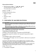
Switching the radio on Short actuation switches the radio on/off Long actuation when the radio is switched on changes it to sleep mode Volume Volume control loud / quiet Memory Storing of the four preferred stations 3. Function 3.1. Intended use • Installation in two flush-type boxes in accordance with DIN EN 49073 (recommendation: deep boxes) • Preferred installation: vertical Order a separate button set for horizontal installation • FM reception in the frequency range 87.5 MHz to 108 MHz 3.2.
4. Operation Switching the radio on/off Press button briefly Device switches on/off The blue LED lights up/switches off L The last selected station is retrieved at the last set volume. Sleep mode The radio is switched on. Press and hold button (approx. 3 seconds). The blue LED flashes. The radio is switched off after approx. 30 minutes. Automatic station scan Press and hold button (approx. 3 seconds) The long actuation is acknowledged by a tone.
Select preferred stations Press the memory button The associated red LED lights up The stored station is received or briefly Volume The button regulates the volume Press the + button louder Press the - button quieter 5. Information for specialist electricians L DANGER! Risk of an electric shock when touching live parts. Electric shock can lead to death. Before working on the device, isolate the connecting cables and cover any active components in the surrounding area. 5.1.
A B 6 fig. 2: Connection power supply L,N Connection AC 230 V~ 1 Connection of extension unit A/B Floating contact L CAUTION! Do not connect any voltage to the floating contact A/B. BA fig.
6. Commissioning After the initial commissioning, an automatic station scan is carried out. The entire frequency range is scanned and stores the four stations with the strongest signal at memory locations 1 to 4. Appendix 7. Technical data Nominal voltage: Frequency: Ambient temperature: Humidity: Frequency range: Type of protection: Connection: AC 230 V ~ 50/60 Hz approx. 0…+ 50 °C approx. 15 % … 90 % no moisture condensation 87.50 MHz … 108.00 MHz IP 20 Screw terminals 2.5 mm² or 2 x 1.
8. Guarantee Guarantee is provided within the framework of legal requirements. Please send the device postage paid with a description of the error to our central Customer Service department: ALBRECHT JUNG GMBH & CO. KG Service Center Kupferstr. 17-19 D-44532 Lünen Service line: +49 23 55 . 80 65 51 Fax: +49 23 55 . 80 61 89 Email: mail.vki@jung.de Technical (general) Service line: +49 23 55 . 80 65 55 Fax: +49 23 55 . 80 62 55 Email: mail.vkm@jung.de Technical (KNX) Service line: +49 23 55 .
Albrecht Jung GmbH & Co. KG Volmestraße 1 D-58579 Schalksmühle Service line: Fax Email: Internet: 0024013702 06.08 +49.23 55.8 06-0 +49.23 55.8 06-1 89 mail.vki@jung.de www.junguk.com www.jung-catalogue.