
Network Router User Manual


NOTE: The services gateway cannot be center-mounted in racks.
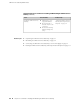
Table 22 on page 53 provides the details on rack size, clearance, and airflow
requirements.
Table 22: Rack Requirements for the Services Gateway
SpecificationsRack Requirements
A 19 in. (48.3 cm) rack as defined in Cabinets, Racks, Panels, and
Associated Equipment (document number EIA-310-D) published by the
Electronics Industry Association (http://www.eia.org).
Rack Size
■
The outer edges of the mounting brackets extend the width of either
chassis to 19 in. (48.3 cm).
■
The front of the chassis extends approximately 0.5 in. (1.27 cm)
beyond the mounting ears.
■
Maximum permissible ambient temperature when two devices are
placed side by side in a 19 in. rack is 40°C.
Rack Requirements
■
The holes within each rack set are spaced at 1 U [1.75 in. (4.5 cm)].
The device can be mounted in any rack that provides holes or hole
patterns spaced at 1-U [1.75 in. (4.5 cm)] increments.
■
The mounting brackets and front-mount flanges used to attach the
chassis to a rack are designed to fasten to holes spaced at rack
distances of 1 U (1.75 in.).
■
The mounting holes in the mounting brackets provided with the
device are spaced 1.25 in. (3.2 cm) apart (top and bottom mounting
hole).
Spacing of Mounting
Bracket and Flange
Holes
Always secure the rack in which you are installing the services gateway
to the structure of the building. If your geographical area is subject to
earthquakes, bolt the rack to the floor. For maximum stability, also
secure the rack to ceiling brackets.
Connecting to the
Building Structure
Related Topics ■ General Site Guidelines for Installing the SRX210 Services Gateway on page 51
■ Site Preparation Checklist for the SRX210 Services Gateway on page 49
■ SRX210 Services Gateway Cabinet Requirements on page 51
■ Clearance Requirements for Airflow and Hardware Maintenance of the SRX210
Services Gateway on page 54
SRX210 Services Gateway Rack Requirements ■ 53
Chapter 7: Preparing the Site for the SRX210 Services Gateway Installation