Allegro DOS ™ OWNER’S MANUAL Allegro DOS Owner’s Manual 1
Manual Part # Release Date: Editor: 2 14649-00 August 2004 R.
Table of Contents Chapter 1 Introduction....................................................... 7 Welcome...................................................................................9 Allegro Overview ....................................................................10 Quick Start Guide ...................................................................12 Chapter 2 Hardware Components .................................. 13 Introduction ...............................................................
Chapter 4 MS-DOS Operating System ........................... 55 MS-DOS Operating System Overview ...................................57 Setting Up Communication .....................................................58 Lynx Windows File Management Utility ..................................61 FileScout DOS File Manager ..................................................67 Text Editor .............................................................................74 Terminal Emulation Program ......................
Chapter 6 Software Developer’s Guide for DOS ......... 117 Introduction to DOS Programmers ....................................... 119 Power Management .............................................................120 Keyboard and Video .............................................................124 Extended BIOS Functions ....................................................125 Hardware Interrupt Listing ....................................................133 I/O Port Mapping ...............................
Allegro DOS Owner’s Manual
▲ Chapter 1 Introduction Chapter 1 Introduction Welcome Allegro DOS Overview Quick Start Guide Allegro DOS Owner’s Manual 7
Allegro DOS Owner’s Manual
Welcome Juniper Systems, Inc. continues to provide cutting edge field computing solutions for agriculture, natural resources, and other rugged field applications. We are pleased to welcome you as a customer. The Allegro Field PC™ is specifically designed for use in extreme field environments. It is rugged, waterproof, and can withstand temperature extremes. The ergonomic, lightweight, balanced design makes it easy to carry and use in the field for extended periods.
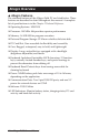
Allegro Overview ▲ Allegro Features The standard features of the Allegro Field PC are listed below. These features are described in detail throughout this manual. A complete list of specifications is in the Chapter 5 Technical Reference.
▲ Standard Accessories The Allegro comes with the following accessories: Allegro Distribution CD-ROM with the Desktop PC Setup Programs, DOS Utility Programs, and Device Drivers NiMH Battery Pack Universal AC Adapter Communication Cable Mini and Full Size Stylus Carrying Straps ▲ Optional Accessories The accessories listed below are optional. Contact your sales representative if you are interested in any of these items.
Quick Start Guide A Quick Start Guide is included with the Allegro DOS. It offers the initial basic steps needed to get the Allegro charged and ready to take out into the field. The instructions on the guide should be done first, before you begin using the Allegro. If the Quick Start Guide is disgarded or misplaced after setting up the Allegro and you discover you need the guide again, you can access a copy of it from the Allegro CD.
▲ Chapter 2 Hardware Components Chapter 2 Hardware Components Introduction Case Design Keyboard Display LED Indicators Batteries Communication Ports PC Cards Slot Sound Generator Expansion Pod Allegro DOS Owner’s Manual 13
Allegro DOS Owner’s Manual
Introduction The Allegro DOS is designed to meet the needs of a user collecting data with a hand-held computer in a rugged field environment using a MS-DOS operating system. This chapter of the manual describes the unique hardware components of the Allegro, including the case, keyboard, display, communication ports, batteries, PC card slot, and expansion pod.
Case Design ▲ Case Features The case has the following features: The polycarbonate ABS material is rugged, shock resistant, and formulated to resist damage from chemicals. The ergonomic shape and smooth edges make it easy to hold, maximizing comfort and usability in the field. The weight distribution is balanced.
▲ Hand Strap and Shoulder Strap There are four metal cleats, one on each corner of the Allegro case. Each cleat has two metal rings that are used to attach the hand strap and shoulder strap onto the Allegro. The straps can be attached in numerous configurations, depending on your preference and whether you are right-handed or lefthanded. The shoulder strap can be used as a neck strap for handsfree operation. The tension on the hand strap is adjustable.
Keyboard ▲ Keyboard Features The keyboard on the Allegro is designed to maximize data entry efficiency and to withstand rugged, wet conditions. Careful planning went into the placement, size, and space between keys to increase efficiency and ease of use. The number keys are large and placed in the center of the Allegro for easy access from either side. Some keys have standard functions as well as special functions accessed with the GOLD and BLUE shift keys.
▲ Special Keys and Key Sequences The standard keyboard letters, numbers, and functions are printed in dark brown on the off-white keys and in off-white on the dark brown keys. These standard options are operational unless a GOLD or BLUE shift key is pressed. Blue key Gold key Blue Shift Key Usage To access the keyboard characters printed in blue, press and release the BLUE shift key followed by the key with the desired blue-lettered character.
Shifted Options The shifted options and the associated key sequences are listed below.
Keyboard Options The following keys and key sequences are functional in DOS. On/Off (Reset) This key is used to turn the Allegro on and off. The ridge around the key helps prevent the Allegro from being accidently turned on without your knowledge (while it is in a backpack, for example). A hard reset is performed by holding down the On/Off key for about 8 seconds. Release the key when the reboot process begins. ❖ Note: When you turn the Allegro on or off, there is no “beep.
Gold Panning key + To pan the display in the direction of the arrow, press the GOLD key plus the right, left, up, or down arrow key. Gold Auto-Panning key + Toggle auto-panning on or off by pressing the GOLD key then the Ins key. (Auto Panning is described later in this chapter under Display, Full Screen, Auto Panning.) Gold Zoom Fonts key + You can toggle between four font sizes by pressing the GOLD key then the Z key.
▲ Cleaning the Keyboard Dirt and debris can get underneath the keyboard bezel. To clean it, use a coin to pull the bezel up at the recess located at the bottom of the keyboard and remove it. We recommend that you use warm water, mild detergent, and a toothbrush to clean the keyboard or simply brush it out. The Allegro remains sealed during this process. (Do not direct a high pressure stream of water at the keyboard to clean it. This action could break the seal, causing water to get inside the Allegro.
Display The Allegro DOS has a high-contrast liquid crystal display. The active viewing area is 3.3” wide x 2.5” high. The display resolution is 320 x 240 pixels. The display is shock-mounted and sealed. ▲ Display Features Contrast: The display contrast can be lightened or darkened. Heater: The display heater allows you to use the Allegro in temperatures below freezing. Backlight: The backlight enhances visibility in low-light conditions. The brightness of the backlight is adjustable.
▲ Adjusting Display Features The display features can be enabled, disabled, or adjusted through the System Setup Program in DOS (see Chapter 4). Some display features can be adjusted using the special key sequences shown below: Display Feature Key Sequence Increase Contrast GOLD + F5 Decrease Contrast GOLD + F4 Backlight Toggle On and Off GOLD + F3 Auto-Panning Toggle On and Off GOLD + Ins Backlight The display backlight is used to enhance visibility in low-light conditions in the field.
Gold key + To toggle between the font sizes, press the GOLD shift key and the Z key (for Zoom). If you are using a program that was written for another hand-held computer with a different screen size, select the font size that best fills the Allegro screen. You can usually avoid making modification to the original program this way. When you develop a new DOS program to run on the Allegro, select a default font that best displays the data on the screen for your application.
Auto-Panning When auto-panning is enabled (the default), the screen automatically shifts (pans) as the cursor moves beyond the visible window. When auto-panning is disabled, the screen does not shift as the cursor moves beyond the visible window. The display screen can be shifted by panning manually or through program control. Autopanning can be turned off in the System Setup Program (see Chapter 4, MS-DOS Operating System, System Setup Program).
LED Indicators The following LED indicators are located above the display: These indicators are active while the Allegro is running, providing you with the following information: LED Description Battery Charge Status: shows the percent of charge remaining in the batteries External Power: indicates that you are connected to an external power source and not drawing power from the internal batteries Charging Indicator: lights up while the rechargeable batteries are charging Solid State Disk Access: flashes w
Batteries The power consumption of the Allegro is very efficient. The Auto Suspend and Power Management features help to conserve power. Maintaining the battery pack and backup supply is simple.
4) Slide the latches downward until they cannot slide any further to securely latch the battery door closed. Do not turn on the Allegro yet. 5) Plug the AC wall charger that came with the Allegro into the wall socket. The small green light on the wall adapter turns on when it is plugged into the wall. 6) Remove the rubber protector from the Allegro’s external power input jack. 7) Plug the power connector end of the wall charger into the Allegro.
Setting the Battery Charge After installing the battery pack into the Allegro, the battery charge percent must be set. This allows the Allegro to know the pack’s charge status. When you insert the battery pack into the Allegro for the first time, the charge status is unknown to the Allegro. To set the charge status of the battery pack after you install the battery pack for the first time, complete the following: 1) Turn on the Allegro by pushing the On/Off button.
3) Press ESC or ENTER to save your settings and exit the Battery Charge Detected screen. The Battery Charge Detected screen closes and the charge status is set. Once the battery pack is fully charged, the gauging automatically sets to 100%. Setting the Battery Charge Percent Based on the status of the battery pack, the following recommendations are designed to help you set the battery charge percent in the Battery Change Detected screen.
If you purchase a battery pack from another vendor, note what the capacity is. For optimum performance, it is best to use battery packs with a 3000 to 4000 mAh capacity. The higher the capacity of the battery pack, the longer it holds a charge. However, battery packs with a capacity over 4000 mAh may not charge fully in the Allegro. As a battery pack ages, it does not operate as long on a charge as it did when it was new. The capacity could be reduced by as much as 50% at the end of its useful life.
Temperature Ranges for Charging the NiMH Battery Pack The Allegro’s NiMH batteries are charged most efficiently at temperatures ranging between 10° to 20° C (50° to 68° F) when the AC power adapter is used. When charging the battery pack keep the temperature of Allegro between 0° to 40° C (32° to 104° degrees F) due to the nature of NiMH batteries. The chart below describes the Allegro battery charging behavior at different temperatures. Temp. Range Temp.
You can run the Allegro from the adapter while the batteries are being charged. To charge the battery complete the following steps: 1) Plug the AC charging adapter into an AC outlet. 2) Insert the connector into the external power input jack located on the top of the Allegro case. It can take up to five hours to fully charge a battery pack. 3) When the batteries are fully charged, the charging circuit switches into trickle charge mode.
Using Vehicle Mode is necessary because every time the key is turned off the Allegro begins a new battery charge cycle. The Allegro circuitry detects when a battery pack is fully charged, however, it takes approximately twenty minutes for this to occur. Repeatedly attempting to charge a fully charged battery pack causes premature degradation in battery performance. In Vehicle Mode, charging is inhibited if the gauging circuitry indicates that battery pack is above 90% charged.
How Battery Gauging Works for the NiMH Rechargeable Battery The Allegro employs a circuit that watches how much charge is added to or removed from the rechargeable battery. For the battery gauging to work correctly on the Allegro, the following values must be known about the NiMH battery pack: - Charge percent - Capacity The battery gauging is set in the following ways: 1) The charge percent and capacity values are set at the factory for the battery pack.
When moving from a cold environment to a warm one the battery charge LED indicators may move up instead of down. This happens because in cold temperatures alkaline batteries have less charge capacity than in warm temperatures and this is reflected in the voltage output. Battery Status LED Indicators There are five LEDs.
If the charging indicator LED does not light up when you plug the Allegro into a charger, the battery has a 90% or higher charge and does not need to be charged. Batteries should be discharged below 80% before they are recharged for maximum battery life. Power Management Features To conserve power, the Allegro has the following built-in power management features: Auto Suspend and Power Manager. These features are controlled through the System Setup Program|Power Management screen.
2) Insert three fresh AA alkaline batteries, taking care to orient them correctly (only use alkaline batteries). Always replace all three batteries at once. Note: For best results, we recommend that you use the new types of alkaline batteries such as the Duracell Ultra™ and Energizer Titanium™. Note: Do not use re-chargeable AA battery adapters. The battery life of three re-chargeable batteries is not cumulative.
Important Information Regarding the Use of Alkaline Batteries The Allegro Field PC is designed to be used with the rechargeable NiMH battery pack that came with the unit. The alkaline battery option should be considered as a backup to the NiMH battery pack, not as the main source of power for an extended period of time. Alkaline batteries have a lower capacity and a higher resistance than NiMH batteries. Thus the battery life and performance of the Allegro are reduced when alkaline batteries are used.
Storing the Allegro for More Than Two Months If you store the Allegro for more than two months, remove the battery pack and attach the AC power adapter to prevent the internal lithium backup battery from draining. When you are ready to use the Allegro, insert a battery pack and fully charge it if necessary. NiMH Battery Pack’s Useful Life Battery packs can be recharged approximately 600 times before they need to be replaced.
If power is not supplied to the Allegro for more than five minutes, the Allegro reboots when the battery pack is replaced or charged. All the programs, data, and applications saved to the disk are safe. Information that was not saved to the disk is lost. The super capacitor should not need replacement through the life of the Allegro. ▲ Backup Battery, Real Time Clock A 3.6 V lithium backup battery supplies current to the Allegro to maintain the real time clock when power is not supplied to the Allegro.
Communication Ports The Allegro DOS has two 9 pin serial ports (located on the top of the case). These ports are recessed to protect them in case of a drop. They are also completely sealed. ▲ 9 Pin Serial Communication Ports The standard 9 pin serial communication ports (COM1 and COM2) allow for the simultaneous operation of two serial devices such as printers, modems, and bar code wands. Additional power is provided on COM1 to power bar code wands and other sensors.
PC Card Slot The Allegro has a user-accessible PC Card Slot (PCMCIA 2.0 Type II) that allows you to add mass data storage and I/O capabilities to your Allegro. The PC card drivers and utilities are factory-installed on the Allegro. These programs provide the card and socket services necessary to operate the card. In DOS, the PC card is the D: drive. ▲ Types of PC Cards Accepted The PC card slot accepts Type I or Type II cards.
4) PC cards have a 68 pin socket on one end. Insert the card socketfirst. The front of the card should be facing the door. ❖ Important Note: Be careful when inserting and removing cards. Excess force could damage the card and the card drive. If the LED indicator for the PC card slot (farthest right) is blinking, the computer is writing to the card. Do not turn off the Allegro and remove the card until the LED stops blinking. Incomplete files can corrupt the data already stored on the card.
Sound Generator The Allegro has the ability to produce basic computer sounds such as beeps and clicks. The key press and screen tap sounds are generated by a secondary processor to reduce power consumption. The sound properties for key presses and screen taps can be adjusted in the System Setup Program|Keyboard|Display Screen. Note that the tone of key presses and screen taps can be adjusted, but the volume cannot.
Expansion Pods Custom expansion pods allow you to integrate additional components as they become available. Options include an RF network, animal ID reader, bar code scanner, GPS receiver (shown below), parallel port, and analog sensor input. Call our Sales Department for information about the availability of these expansion pods. Expansion pods replace the PC card door. The Allegro remains sealed when an expansion pod is installed.
▲ Chapter 3 Memory Configuration and Data Storage Options Chapter 3 Memory Configuration and Data Storage Options Internal Memory Program and Data Storage Options Allegro DOS Owner’s Manual 49
Allegro DOS Owner’s Manual
Internal Memory The Allegro’s internal memory is configured much like the memory in laptop computers. It consists of ROM (Read Only Memory) and RAM (Random Access Memory). ▲ Read Only Memory (ROM) ROM is used to store the Operating Systems, BIOS, and Utility programs. The files on the A: drive of the Allegro are located in the ROM. Information in the ROM is electronically “burned” into a chip before the chip is installed at the factory. Information stored in ROM can be read or copied.
Program and Data Storage Options The Allegro has two options for storing programs and data: a solid state hard disk and a PC card slot for memory cards. ▲ Storage Designations The solid state disk and PC memory cards are accessed by typing in their drive assignment letters at the DOS prompt as follows: Drive Type of Storage C: Solid State Hard Disk D: PC Card ▲ Solid State Hard Disk The Allegro has a 24 M solid state hard disk used to store programs and data.
The PC card slot accepts Type I or Type II cards. These cards include ATA Flash cards, SRAM (Static Random Access Memory), and Compact Flash cards. All types of cards have a 68 pin connector for attachment to the Allegro. The cards must be 5 V or 5 V/3 V (PC cards that are 3 V only are not supported). This is a 16 bit card slot. It is not a card bus slot. A PC memory card is a solid state, self-contained memory board housed in a credit card-sized package. These cards behave like hard disks.
Replacing SRAM Card Batteries SRAM card batteries are readily available at most stores. Unless the manufacturer’s instructions state otherwise, we recommend that you change the battery every six months. Formatting SRAM Cards SRAM cards come pre-formatted. Files and directories can be copied onto it just like a standard disk drive.
▲ Chapter 4 MS DOS Operating System Chapter 4 MS-DOS Operating System MS-DOS Operating System Overview Setting Up Communication Lynx Windows File Management Utility FileScout DOS File Manager Text Editor Terminal Emulation Program System Setup Program Startup Files DOS Utility Programs and Device Drivers Make Space Utility Program Serial Printing Utility Program Allegro DOS Owner’s Manual 55
Allegro DOS Owner’s Manual
MS-DOS Operating System Overview This Chapter describes the operation of the Allegro using the MS-DOS™ 6.22 operating system. ▲ Running DOS You can operate the Allegro by issuing standard DOS commands from the DOS prompt or through a file management program called FileScout (described in detail later in this chapter). ▲ Programs for the Desktop PC and the Allegro Desktop PC Program The Allegro Distribution CD-ROM includes the Lynx™ Windows File Manager for installation onto your desktop PC.
Setting Up Communication Communication functions are handled by the following programs: On the desktop PC: Lynx™ File Management Utility On the Allegro: FileScout™ DOS File Management Utility ▲ Establishing Communication Between Computers Follow the steps listed below to set up communication between the desktop PC and the Allegro: 1) Connect one end of the serial communication cable to the serial port on the desktop PC and the other end to either one of the serial communication ports on the Allegro (CO
Once communication is established, the drives, folders, and files located on the Allegro are shown on the Lynx remote screen on the desktop computer. On the Allegro FileScout status line, the word Connected blinks every second to indicate that a connection is made with the computer. Refer to the information about Lynx later in this chapter for details.
F6 - Lynx To communicate with Lynx, the Allegro needs to be in the Lynx communication mode. When Lynx mode is on, the word Lynx is displayed at the top of the FileScout menu along with the active port as shown below: FileScout v1.0 Lynx – COM1 When the Allegro is in Lynx mode, it checks at regular intervals to see if it is linked to a computer. When it detects a connection, the Allegro is treated as a remote computer by the desktop computer. To turn Lynx mode on or off, Press F6 and make a selection.
Lynx Windows File Management Utility Lynx is a Windows file management utility that runs on a desktop PC, allowing you to easily transfer files between your desktop PC and the Allegro Field Computer.
▲ Lynx Menu Options Once communication has been established between the Allegro and the PC, you can use the Lynx menu options. Shortcut buttons are available for some of these options. The shortcuts are described later in this chapter. File Menu Options The following are available on the File Menu: New Folder Delete Filters Exit New Folder Creates a new folder or sub-folder on the local or remote computer. A dialog box is shown where you type in the new folder name. Delete Deletes a file or a folder.
Edit Menu Options The edit options follow standard Windows protocol. Highlight the file or folder you want to perform the editing function on. You can select multiple files with Select All or by holding down the Shift or Ctrl key as you highlight each file. Choose the editing option you want to perform in one of the following ways: 1) Select the option from the Edit Menu (Edit/Cut for example). 2) Press the appropriate control key shortcut (Ctrl X for example).
Connect to Remote Establishes a connection between the PC and the Allegro. Send to Remote Sends a file from the PC (Local) to the Allegro (Remote). To do this, complete the following steps: 1) Highlight the file or files to transfer. You need to rename files that are more than eight characters long before you transfer them to the Allegro. 2) Select the Send to Remote menu option or press the shortcut button to send the file(s).
Select COM Port Select the COM port that the communication cable is connected to on your PC. Help Menu Option The following options are available on the Help Menu: Contents Index Using Help MS-DOS Help About Contents A Table of Contents for Lynx Help. Index An Index for Lynx Help. Using Help Describes how to use Help. MS-DOS Help The MS-DOS 6.22 commands are listed and described. To read about a specific command in detail, select it from the menu. You can view or print this information.
Connect The Connect button is used to establish a connection between the PC and the Allegro (the same as the Transfer/Connect to Remote function). Up Arrow The Up Arrow button is used to send a file from the Allegro to the PC (the same as the Transfer/Receive from Remote function). Down Arrow The Down Arrow button is used to send a file from the PC to the Allegro (the same as the Transfer/Send to Remote function).
FileScout DOS File Manager FileScout is a DOS File Management Utility that runs on the Allegro. Instead of issuing commands at the DOS prompt, you select options displayed on menus to perform file management activities. Fewer keystrokes are required than with the standard DOS command line environment.
Title The name and version of the program, communication mode, and active COM port are indicated on the first line of the display. On the sample screen shown on the previous page, the program name and version number is FileScout v1.0c. The word Lynx is shown, indicating that the Lynx communication mode is turned on. The active communication port is COM1. First Status Line On this line the current drive, directory and subdirectory (if applicable) are listed.
ENTER Key The ENTER key is used to execute an implied command. The command that takes effect when ENTER is pressed depends on which file or folder is highlighted. There are three implied commands: 1) Change drive: To change drives, press F1. A list of available drives is shown. Highlight the drive you want to select and press ENTER. The letter of the current drive is displayed on the first status line. 2) Change folder: To change folders, highlight the desired name and press ENTER.
F1 Drives Press F1 and a list of available drives is shown. Highlight the drive you want to select and press ENTER. The letter of the selected drive is displayed on the first status line on the FileScout main screen. F2 Edit The edit function is used to edit existing text files. Highlight the file you want to edit and press F2. The file is opened in the Text Editor. To create a new text file, see the description for F10 Utilities, option 2, Editor. F3 Copy This command copies a file or a group of files.
F6 Move This command moves a file or a group of files to other drives or directories. Highlight a file or mark a group of files to be copied using Ins and press F6. You are asked to enter the destination for the files to be moved to on the second status line. Enter the destination path (drive and directory). Press ENTER to move the file(s). ❖ Note: You cannot move files to the ROM drive (A:) F7 Rename To rename a file, highlight the desired file and press F7. Enter the new filename and press ENTER.
3. SetUp Executes the DOS SetUp program. (See DOS Setup Program later in this chapter for details.) 4. File Filter Displays all or a subset of files on the current directory. You can set a mask on the types of files you want to display. For example, if you only want to display files with the extension .DAT, you would use the File Filter utility to set the mask *DAT. The default setting for the File Filter is *.* which shows all files.
Before you can delete a subfolder, you must delete all of the files in it, then complete the following steps: 1) Highlight the subfolder. 2) Press Del key. When the Del key is pressed, you are asked to confirm the deletion of the file(s) or subfolder. You must type in Y followed by ENTER if you want to proceed with the deletion. Any other keystroke aborts the file deletion. ❖ Note: You cannot delete files from the ROM drive (A).
Text Editor There is a full screen text editor available that runs on the Allegro. The text editor allows you to create and edit text files up to 64 K in size. It is useful for editing the AUTOEXEC.BAT and the CONFIG. SYS files. ▲ Starting a New Text File Press F10 Util from FileScout to bring up the Utilities menu. Select 2 Editor to execute the Text Editor program. Enter a name for the new file on the second status line after the word File: and press ENTER. A blank page appears on the screen.
To move the cursor one character at a time, the arrow keys are used: To the right Right Arrow To the left Left Arrow Up one line Up Arrow Down one line Down Arrow To move the cursor to the start or end of a line: To the beginning of a line BLUE key + Home To the end of a line BLUE key + End To move the cursor one screen To previous screen To next screen BLUE key + PgUp BLUE key + PgDn To move the cursor to: The beginning of the file The end of the file Ctrl + BLUE key + PgUp Ctrl + BLUE key + PgDn To pa
Function Keys The function keys are used for editing files as follows: Function F1 F2 F3 F4 F5 F6 F7 F8 F10 Esc Ins Description Paste Mark Undelete Line Undelete Character Print Block Cut Delete to End of Line Delete Line External Display Exit Insert Inserting and Overwriting Text You can enter text in insert mode or overwrite mode. Insert mode is the default. The word Ins is displayed at the bottom right corner of the display.
Undeleting Text Text deleted with the Del or BkSp key can be restored at the cursor location as long as the cursor has not moved to another line. (Once the cursor is moved using the arrow keys the text is lost and cannot be recovered.) To undelete the removed text, press the F4 key. Text removed using F7 (clear to end of line) cannot be recovered. Lines deleted using the F8 key can be pasted back anywhere in the document by pressing the F3 key.
Terminal Emulation Program The Terminal Emulation program is used to test communication protocol settings and hardware connections between the Allegro and another device such as a bar code wand, GPS receiver or another computer. Connect the device to the Allegro and set up the communication parameters. Press F10 Util from FileScout to bring up the Utilities menu. Select 1 Terminal to execute the Terminal Emulation program.
Split Screen Binary/ASCII (default) shows binary data coming in on the top section of the screen and ASCII data on the bottom section of the screen. Split Screen Remote/Local shows the data coming in from the remote device on the top section of the screen and the data going out from the Allegro to the remote device on the bottom section of the screen.
System Setup Program The Setup program is used to configure your Allegro DOS Field PC. The parameters you edit with Setup include: System Date and Time Processing Speed Keyboard Configuration Display Configuration Auto-Panning (On or Off) Power Management ▲ Executing Setup The easiest way to invoke the Setup program is by pressing the GOLD key plus the S from any screen in DOS. The main menu screen pops up. Setup is resident on the system ROM (A:) and can be executed from FileScout or directly from DOS.
The parameters and options found on the Setup screens are described on the following pages. The default values are underlined. You can select and edit the parameters using the keystrokes listed below. Key Function Arrow Keys Move between parameters. F1 Scroll through options starting with the previous value. F2 Scroll through options starting with the next value. ENTER Select highlighted option. ESC Exit current Setup screen and return to the main menu.
Configuration Screen Date Month=Jan-Dec, Day=1-31, Year=1980-2099 Time Seconds=0-59, Minutes=0-59, Hours=0-23 Time is expressed in the standard 24 hour format (military time). Boot Options C then A, A then C Power Management Screen Power Key (On/Off Key): Suspend/Resume or On/Off In Suspend/Resume mode, the system becomes suspended when the On/Off key is pressed or when the preset Auto Suspend time interval is reached (5 to 75 minutes, see below).
In On/Off mode, the system clears and reboots when the On/Off key is pressed. If external power is connected to the Allegro, the Allegro goes into a semi-low power state where it appears to be off, but it is actually on. Any event that normally causes the Allegro to turn on (pressing the On/Off key, com port ring in, etc.) causes the Allegro to reboot. When the external power is removed, the Allegro powers off.
When the Power Manager is Off, the processor runs at the same speed all the time regardless of activity. The following table gives clock speeds in MHz for the five performance levels with the Power Manager On or Off. Performance Setting Hyper High Medium Low Miser Power Manager On 100/4 66/4 33/2 16/1 8/1 Power Manager Off Processing/Idle 66 33 16 8 2 ❖ Note: When alkaline batteries are used, the processor speed is limited to 33 MHz for all settings.
Keyboard/Display Screen Key Tone: Low, Medium, High Sets the frequency of the speaker for key clicks. Key Click: On or Off When On is selected, an audible beep is sounded when a key is pressed. When Off is selected, there is no sound. Auto-Pan: Enabled or Disabled When auto-panning is On, the screen pans as the cursor moves beyond the visible window. When it is Off, the screen does not pan when the cursor leaves the visible window.
Video Map (Text Mode Only): B/W1, B/W2, Gray Scale This feature controls how CGA colors are mapped to the LCD: black and white (B/W1 or B/W2) or 16 shades of gray (Gray Scale). Both B/W settings map the attribute byte for each character on the screen to either black on white (normal) or white on black (inverted). Values for the foreground and background attributes are computed based on RGBI content. The attribute with the highest value is assigned black, the other is assigned white.
Font Size: 8x8, 8x12, 10x12, 16x16 This field lets you select the font size for text mode. The units are character width x height in pixels.
Restore Defaults Screen This screen allows you to return all the System Setup Parameters to the factory defaults. If you wish to do this, press Y. If you do not want to reset the defaults, press N.
Startup Files AUTOEXEC.BAT and CONFIG.SYS startup files containing default configuration information are factory installed on the C: drive of the Allegro. Each time you turn on or reboot into DOS on the Allegro, DOS searches for these files and carries out their commands. (Note: If the Allegro is booted from the A: drive, the CONFIG.SYS and AUTOEXEC.BAT files on C: are not executed.) ❖ Important Note: It is important that the existing CONFIG.SYS and AUTOEXEC.
The CONFIG.SYS file can also contain the following special characters: ; Specifies that the current line is a descriptive comment and should not be carried out. Insert this character at the beginning of the line. (You can also insert a comment by using the REM command.) ? Specifies that DOS is to ask for confirmation before carrying out the current command. Insert this character immediately after the command you want to prompt for, without any intervening spaces, but before the equal sign (=).
▲ Changing the CONFIG.SYS File You can modify the CONFIG.SYS file using a text editor. If you need to make changes or additions to the CONFIG.SYS file, we recommend that you modify the existing CONFIG.SYS file found in the root directory on the C: drive. You can add command lines to your CONFIG.SYS file that tell the system to automatically load a specified program. If you need to add additional device drivers or commands, add them at the end of the existing CONFIG.SYS file.
Default AUTOEXEC.BAT File on the Allegro The AUTOEXEC.BAT file is stored in the root directory of the C: drive. A backup copy is also stored in the C:\UTIL directory. The file is configured as follows: Path = c:\;c:\util;c:\dos; a:\: prompt $p$g loadhigh doskey loadfont Changing the AUTOEXEC.BAT File You can modify the AUTOEXEC.BAT file using a text editor. If you need to make changes or additions, we recommend that you modify the existing AUTOEXEC.BAT file found in the root directory on the C: drive.
Bypassing Individual Commands If you suspect your problems are related to a specific command, you can view each command individually and bypass only the command you think may be causing the problems. To review individual commands, follow these steps: 1) Reboot the Allegro by pressing the On/Off key for 8 to 10 seconds (just until the screen clears). After the system starts, DOS displays the following message: Starting MS-DOS... 2) While the text is on your screen, quickly press and release the F8 key.
DOS Utility Programs and Device Drivers A subset of the most commonly used DOS commands is stored on the C: drive of the Allegro. A full set of the DOS commands is located on the Allegro Distribution CD-ROM. You can access information about the DOS commands using one of the following methods: On your PC, the Lynx File Management Utility has a MS-DOS Help function. Select Help/MS-DOS Help to run this function. The Help is a DOS program that runs in a DOS window.
* ATTRIB Displays or changes file attributes. + BREAK Sets or clears extended CTRL+C checking. + CHDIR Changes the current directory. + CD Short name for CHDIR command. * CHKDSK Checks a disk and displays a status report. + CLS Clears the screen. * COMMAND Starts a new instance of the MS-DOS command interpreter. + COMP Compares the contents of two files or sets of files. + COPY Copies one or more files to another location. + CTTY Changes the terminal device used to control your system.
* FDISK Configures a hard disk for use with MS-DOS. * FIND Searches for a text string in a file or files. * FORMAT Formats a disk for use with MS-DOS. GRAPHICS Loads a program that can print graphics. * HELP Provides complete, interactive Help information for MS-DOS commands. * HIMEM.SYS A device driver that controls programs and data in extended memory. # INTERLNK Connects two computers via parallel or serial ports. # INTERSVR Starts the Interlnk server.
* SCANDISK Checks a drive for errors and repairs any problems it finds. + SET Displays, sets, or removes MS-DOS environment variables. * SETVER Sets the version number that MS-DOS reports to a program. # Installs file-sharing and locking capabilities on your hard disk. SHARE * SORT Sorts input. * SUBST Associates a path with a drive letter. * SYS Copies MS-DOS system files and command interpreter to a disk you specify. + TIME Displays or sets the system time.
Make Space Utility Program MKSPACE.BAT is a batch program that removes DOS utility programs that are not commonly used from the DOS directory on the C: drive of the Allegro. This utility frees up approximately 1 M of space on the C: drive. MKSPACE.BAT is located on the Allegro in C:\DOS. Below is a list of the utility programs that are removed when the MKSPACE.BAT program is run. debug.exe deltree.exe edit.com edit.hlp fc.exe find.exe help.com help.hlp label.exe more.com move.exe qbasic.hlp qbasic.
Serial Printing Utility Program SERPRN.EXE is a DOS utility program that allows you to set up an Allegro serial communication port to send output to a printer. If a program is designed to use a parallel printer port, SERPRN redirects the parallel port settings to a serial port. It also sets the communication parameters and software and hardware handshaking. This program can be used in place of the Mode command. Like the Mode command, you can call SERPRN from the AUTOEXEC.
Example uses of SERPRN are shown below. Syntax Serprn com1 9600 n 8 1 x t10 Output HM/JS Parallel to Serial Redirector COM1 9600 n 8 1 LPT1 redirected to COM1 Handshaking XON If the program is called with only the COM port specified, the program default settings are used.
▲ Chapter 5 Technical Reference Chapter 5 Technical Reference Specifications Glossary of DOS Terms BIOS Messages Files Located on the Solid State Disk Solid State Disk Utilities PC Card Utilities and Drivers Communication Cable Schematic Allegro DOS Owner’s Manual 101
Allegro DOS Owner’s Manual
Specifications ▲ Processor AMD SC 400, 486 AMD processor, 100 MHz ▲ Operating Systems MS-DOS® 6.22 ▲ Programs (for Allegro and PC) DOS Utilities - Desktop PC: Lynx™ File Transfer Utility - Allegro Utilities: FileScout™ DOS File Manager, Text Editor, Terminal Program ▲ Physical Specifications Size: 10” high x 5.25” wide at display x 3.1” wide at narrowest point x 1.5” deep (256 mm x 133 mm x 79 mm x 38 mm) Weight: 1.
Active viewing area: 3.3” wide x 2.5” high (4.
Compatible with ATA Flash, SRAM, or I/O cards Compact Flash card adapter is available ▲ Power Rechargeable NiMH quick change battery pack (replacements are readily available) NiMH batteries last 10 to 16 hours between charges during typical use; actual battery life can be longer or shorter, depending on the application, backlight and heater usage, and power management Alkaline battery holder uses 3 AA alkaline cells (optional) Battery charge status LED indicators, low battery warning Resume m
Glossary of DOS Terms Following is a glossary of some basic terms relating to the operating systems, memory, and data storage options. ▲ AUTOEXEC.BAT File An AUTOEXEC.BAT startup file contains default configuration information. There is an AUTOEXEC.BAT file on both the Allegro’s C: and A: drive. The Allegro usually boots from the C: drive. Therefore, the AUTOEXEC.BAT on the C: drive is activated first. It does not chain to A:. You can modify this file as needed for your application.
▲ Disk-On-Chip (Hard Disk) A disk-on-chip is a solid state disk drive. The C: drive on the Allegro is a disk-on-chip. It can be read from and written to just like the hard drive on a PC but has no moving parts and does not require power to maintain contents. ▲ Kilobyte One kilobyte (K or KB) is thought of as one thousand bytes (the actual figure is 1,024 bytes). ▲ Megabyte One megabyte (M or MB) is thought of as one million bytes (the actual figure is 1,048,576 bytes).
ASCII Character Sets When in DOS, any character code from the IBM standard (0-127) or extended(128-255) character set may be entered by pressing and holding the Alt key while keying in the character code on the number keys. The ALT-nnn function can be enabled (default) or disabled through the extended BIOS function 2E11h.
▲ Extended ASCII Character Set Allegro DOS Owner’s Manual 109
BIOS Messages ▲ Power On Self Test When the Allegro powers up, it goes through a series of internal tests and diagnostics. This is called the Power On Self Test (POST). During these tests, messages are displayed on the screen or a series of beeps are heard. If you see an error message during this process, try resetting the Allegro by holding the On/Off key down for 8 seconds. If the error persists, contact our Customer Service Department.
Files Located on the Solid State Disk The main data and program storage used in the Allegro is a solid state disk-on-chip manufactured by M-Systems™. It operates much the same as a desktop PC hard drive, but with no moving parts. The following files are factory installed on the solid state disk. Copies of these files are also located on the Allegro Distribution CDROM. The drive designations are C: for DOS. ▲ C:\ AUTOEXEC.BAT CONFIG.SYS COMMAND.COM NK.BIN (hidden) ▲ C:\UTIL AINFO.EXE AINFO.TXT ATAINIT.
▲ C:\DOS ANSI.SYS ATTRIB.EXE CHKDSK.EXE CHOICE.COM DEBUG.EXE DEFRAG.EXE DELTREE.EXE DOSHELP.HLP DOSKEY.COM EMM386.EXE EDIT.COM EDIT.HLP FC.EXE FIND.EXE HELP.COM HELP.HLP HIMEM.SYS LABEL.EXE MEM.EXE MKSPACE.BAT MODE.COM MORE.COM MOVE.EXE POWER.EXE ▲ C_Program Files PTAB.EXE CALC.EXE 112 Allegro DOS Owner’s Manual PRINT.EXE QBASIC.EXE QBASIC.HLP QBASIC.INI SCANDISK.EXE SCANDISK.INI SETVER.EXE SORT.EXE SUBST.EXE TREE.COM UNDELETE.EXE XCOPY.
Solid State Disk Utilities Some disk-on-chip utility programs are factory installed on the solid state disk. They are also included on the Allegro Distribution CDROM. When in DOS, these files allow you to view the status of the disk and to reprogram it if necessary. Name Type Description DDEFRAG EXE Used to defragment the contents of the C: drive. Run this on a monthly basis to keep the solid state disk running at optimum performance. DFORMAT EXE Used to format the Disk on Chip.
PC Card Utilities and Drivers ▲ Factory Installed Programs and Drivers In DOS, the PC card slot is operated by CardSoft™ PC card utility programs and device drivers from System Soft™. They are factory installed on the C: drive of the Allegro and are also located on the Allegro Distribution CD-ROM. These programs and drivers are listed below (for the proper loading order, see the sample CONFIG.SYS file in Chapter 4). ❖ Note: All of the “.
Name Type Description IBM3270 CLB IBM 3270 network cards IBMLAN CLB IBM network cards IBMTOK CLB IBM token ring network cards INTELLAN CLB Intellan denwork cards LINKSYS CLB Link Systems network cards LINKSYS2 CLB Link systems network cards PROXIM CLB Proxim network cards SOCKETEA CLB SUNDISK5 CLB Sundisk (Sandisk) cards TDKLAN2 CLB TDK network cards WD CLB Western Digital cards XIRCOM CLB Xircom network cards ▲ Programs for Other PC Card Types and Brands The following f
Communication Cable Schematic A wiring diagram for the serial communication cable is shown below.
▲ Chapter 6 Software Developer’s Guide for DOS Chapter 6 Software Developer’s Guide for MS-DOS Introduction Power Management Keyboard and Video Extended BIOS Functions Hardware Interrupt Listing I/O Port Mapping AT Keyboard Scan Codes Keyboard Key-Code Tables Allegro DOS Owner’s Manual 117
Allegro DOS Owner’s Manual
Introduction to DOS Programmers This chapter of the manual includes technical information for DOS programmers. The power management information enables programmers to run the Allegro Field PC as efficiently as possible in terms of speed and power consumption. The keyboard and video interrupt functions can be used to control the keyboard and video screens.
Power Management The Allegro has several power management functions integrated within the BIOS. Applications can use these functions to greatly enhance performance and operating time between battery charges. There is an internal automatic Power Manager, which can be set off or on, and five levels of performance, from 0 (miser) to 4 (hyper). There is a trade-off between battery operating time and performance.
For applications that do not take advantage of the Allegro power API, the BIOS Automatic Power Manager can greatly extend operating time and should be used when possible. In our experience, it works quite well with most applications. However, because the BIOS can only guess what the processor is doing, in some cases it may shut activities down when it should not and vice versa. If the program is misbehaving with Power Manager enabled, try disabling it.
▲ Allegro Get Keystroke Function (Allegro_Getch()) The following function can be used to put the Allegro to sleep while waiting for a keystroke.
▲ Allegro CPU Done Function (Allegro_CpuDone) This function is called to restore the Power Manager to the normal state after a CPU busy call.
Keyboard and Video A programmer can use the keyboard and video interrupt functions to control the keyboard and video screens. These functions are described below. ▲ Keyboard Intercept Functions BIOS interrupt 15h function 4Fh can be hooked to intercept raw (not yet translated) scan codes from the keyboard, which are contained in the AL register. The scan codes at this level are unique to the Allegro. Refer to the system scan codes in the Scan Code Tables found at the end of this chapter.
Extended BIOS Functions Extended BIOS services are available through the use of an extended interrupt function BIOS call. The functions are placed in register AH. The subfunctions are placed in register AL. You then invoke INT 10h. When the subfunction requires data input (for example, to set the contrast), the data byte or word is generally passed in register BL or BX. The output byte is returned in register AL. An unsuccessful operation exits the function with the carry bit set.
▲ Function AH=2Eh Note: The behavior of the panning sub-functions 00 - 03 depends on the current font size and video mode. Subfunction: AL = 00h (pan left) Pans screen left. If screen is at leftmost limit, no action is taken. Returns nothing.
Subfunction: AL = 01h (pan right) Pans screen right. If screen is at rightmost limit, no action is taken. Returns nothing. Subfunction: AL = 02h (pan up) Pans screen up. If screen is at top of 25 row virtual display, no action is taken. Returns nothing. Subfunction: AL = 03h (pan down) Pans screen down. If screen is at bottom of 25 row virtual display, no action is taken. Returns nothing.
WARNING: CPU busy drains the batteries rapidly and should only be enabled when needed. Returns nothing. Call with: BL=00h BL=01h CPU busy CPU done Subfunction: AL = 0Ch (disable BIOS power manager) Disables automatic power management functions in the BIOS. The Allegro generally uses less power with power manager enabled. Returns nothing. Subfunction: AL = 0Dh (enable BIOS power manager) Enables automatic power management functions in the BIOS.
Subfunction: AL = 14h (select font size in text mode) Call with: b1 = 00h return current setting in AL 01h set 8 x 8 pixels 02h set 8 x 12 pixels 03h set 10 x 12 pixels 04h set 16 x 16 pixels Subfunction: AL = 15h (perform system hard reset) No arguments, when called does a hard reset. Subfunction: AL = 19h (set LED brightness) Call with: b1 = 00h return current setting in AL = 01h dim = 02h medium = 03h bright Subfunction: AL = 1Ah (get battery % charge) Returns AL = % C, range 0 to 100%.
▲ Function AH=2Fh Subfunction: AL = 00h (read status byte) Output: AL = Status Byte, where: Subfunction: AL = 01h (read video contrast) Output: AL = Video Contrast The range of video contrast is from 0 to 63. Subfunction: AL = 0Ch/AL = 0Dh (turn backlight off/on) AL = 0Ch turns the display backlight off. AL = 0Dh turns the display backlight on. Returns nothing. Subfunction: AL = 0Eh/AL = 0Fh (set heater off/auto) AL = 0Eh turns the display heater off. AL = 0Fh sets the display heater to automatic.
Subfunction: AL = 15h (set auto suspend duration) This subfunction requires an input value to set the auto suspend duration. The input value is passed in the BL register. There is no output.
Subfunction: AL = 1Ah/AL = 1Bh (set auto-panning off/on) There is no output for these subfunctions. AL = 1Ah turns autopanning off. AL = 1Bh turns auto-panning on.
Hardware Interrupt Listing The following chart shows the interrupt-level assignments in decreasing priority.
I/O Port Mapping Address Function 080 2F0 - 2F3 2F8 - 2FF 300 - 31F 3D0 - 3DF 3E0 - 3E7 3F8 - 3FF Diagnostics Port System Control Registers COM2: Internal - Do Not Use CGA Display PC Card Controller COM1: 134 Allegro DOS Owner’s Manual
AT Keyboard Scan Codes The scan codes on the Allegro keyboard have been configured as shown in the following chart: Shft, Ctrl, Can be configured to use Alt scan codes for either right, left, or both sides (default) of AT keyboard (see extended BIOS function 2E11h) Home, PgUp PgDn, End, Ins, Del Uses scan codes from dedicated (gray) keys on AT keyboard Arrow Keys dedicated (gray) keys on AT keyboard Uses scan codes from Number Keys keyboard (not the 10-key keypad) Uses scan codes from top row keys of A
Allegro DOS Owner’s Manual 38 5B 0F 76 44 3F 77 43 3E 75 42 3D 58 41 3C 57 40 3B 1D Contrast - Contrast + Backlight F12 F11 Gold Alt Back Tab F10 F9 F8 F7 F6 Blue System Scan Codes (hex) Ctrl Tab F5 F4 F3 F2 F1 Normal Keyboard Legend oF/00 0F/09 44/00 3F/00 43/00 3E/00 42/00 3D/00 86/00 41/00 3C/00 85/00 40/00 3B/00 Normal 0F/00 0F/00 5D/00 58/00 5C/00 57/00 5B/00 56/00 88/00 5A/00 55/00 87/00 59/00 54/00 Shift Character Codes 94
Allegro DOS Owner’s Manual 137 5 4 Ins 9 8 7 BkSp Esc Normal 5 4 PgUp ? 9 8 7 TS Brk Blue Keyboard Legend Pan Up Gold 06 06 05 05 72 49 48 61 52 0A 0A 09 09 O8 08 7C 0E 70 01 System Scan Codes (hex) 06/35 06/35 05/34 05/34 49/E0 48/E0 35/3F 52/E0 0A/39 0A/39 09/38 09/38 08/37 08/37 0E/08 01/1B Normal 06/35 06/35 05/34 05/34 49/E0 48/E0 35/3F 52/E0 0A/39 0A/39 09/38 09/38 08/37 08/37 0E/08 01/1B Shift Character Codes 84/E0 4D/
Allegro DOS Owner’s Manual Del 3 2 1 6 Normal PgDn ! 3 2 1 End Home 6 Blue Pan Left Gold Pan Down Pan Right Keyboard Legend 74 51 50 5F 53 04 04 03 03 02 02 73 4F 4D 71 47 4B 07 07 System Scan Codes (hex) 51/E0 50/E0 02/21 53/E0 04/33 04/33 03/32 03/32 03/31 02/31 4F/E0 4D/E0 47/E0 4B/E0 07/36 07/36 Normal 51/E0 50/E0 02/21 53/EO 04/33 04/33 03/32 03/32 03/31 02/31 4F/E0 4D/E0 47/EO 4B/E0 07/36 07/36 Shift Character Cod
Allegro DOS Owner’s Manual 139 F E D C B A Enter .
Allegro DOS Owner’s Manual O N M L K J I H G Normal } { & | = + ) ( > Blue Keyboard Legend Gold 6E 18 59 31 6D 32 64 26 0D 25 65 24 5E 17 5C 23 6A 22 System Scan Codes (hex) 1B/7D 18/6F 1A/7B 31/6E 08/26 32/6D 2B/7C 26/6C 0D/3D 25/6B 0D/2B 24/6A 0B/29 17/69 0A/28 23/68 34/3E 22/67 Normal 1B/7D 18/4F 1A/7B 31/4E 08/26 32/4D 2B/7C 26/4C 0D/3D 25/4B 0D/3B 24/4A 0B/29 17/49 0A/28 23/48 34/3E 22/47 Shift Character Codes 18/0F 3
Allegro DOS Owner’s Manual 141 X W V U T S R Q P Normal ; , ^ ] [ $ # @ % Blue Keyboard Legend Gold 27 2D 33 11 66 2F 1B 16 1A 14 67 1F 68 13 6C 10 62 19 System Scan Codes (hex) 27/3B 2D/78 33/2C 11/77 07/5E 2F/76 1B/5D 16/75 1A/5B 14/74 05/24 1F/73 04/23 13/72 03/40 10/71 06/25 19/70 27/3B 2D/58 33/2C 11/57 07/5E 2F/56 1B/5D 16/55 1A/5B 14/54 05/24 1F/53 04/23 13/52 03/40 10/51 06/25 19/50 Shift Character Codes Normal 2D/18 11
Allegro DOS Owner’s Manual Task Start Toggle Font 7D 7B 7A 60 63 “ 7F _ 3A Gold CapLk 2A 7D 28 2C 29 15 Shift Toggle Font Gold 39 ‘ ` Blue System Scan Codes (hex) Space Z Y Normal Keyboard Legend CF/00 BF/00 28/22 0C/5F 39/20 28/27 2C/7A 29/60 15/79 Normal DF/00 EF/00 28/22 0C/5F 39/20 28/27 2C/5A 29/60 15/59 Shift Character Codes AF/00 FF/00 0C/1F 39/20 2C/1A 15/19 Ctrl AH/AL AF/00 FF/00 28/00 82/00 39/20 28/00 2C/00 29/00 15/00 Al
▲ Chapter 7 Warranty, Repair Information, and Software License Agreements Chapter 7 Warranty, and Software License Agreement Warranty and Repair Infromation Software License Agreement Allegro DOS Owner’s Manual 143
Allegro DOS Owner’s Manual
Warranty and Repair Information ▲ Limited Warranties Juniper Systems, Inc. (referred to as JS) warrants that all Allegro Field Computer hardware components (except for the items listed below) shall be free from defects in materials and workmanship for a period of 12 months from the date of shipment when properly installed, calibrated, and operated in accordance with instruction manuals accompanying said hardware and used for the purpose for which said hardware was designed.
Factory Sealed Unit The Allegro is a factory sealed unit. There are no internal user serviceable parts. If the Allegro is opened or in any other way tampered with, all warranties are null and void. Updates or Modifications JS shall be under no obligation to update or modify its products except as herein noted to correct defects or errors.
Software License Agreements ▲ Juniper Systems This Software License Agreement is between the end-user and Juniper Systems, Inc. Please read the following terms and conditions before using the Allegro Field PC and the software created by JS for use with the Allegro. This agreement supersedes any prior agreement, written or oral. Programs created by another company and distributed with the Allegro are subject to the license agreements created by these companies for their products.
▲ Microsoft End User License Agreement The Allegro Field PC includes software licensed by Juniper Systems, Inc. from Microsoft Licensing Inc. or its affiliates (“MS”). Those installed software products of MS origin, as well as associated media, printed materials, and “online” or electronic documentation (“SOFTWARE”) are protected by copyright laws and international copyright treaties, as well as other intellectual property laws and treaties. The SOFTWARE is licensed, not sold.
- Limitations on Reverse Engineering, Decompilation, and Disassembly. You may not reverse engineer, decompile, or disassemble the SOFTWARE, except and only to the extent that such activity is expressly permitted by applicable law notwithstanding this limitation. - SOFTWARE TRANSFER ALLOWED BUT WITH RESTRICTIONS. You may permanently transfer rights under this EULA only as part of a permanent sale or transfer of the Device, and only if the recipient agrees to this EULA.
Allegro DOS Owner’s Manual
▲ Chapter 8 Expansion Pod Chapter 8 Expansion Pod GPS Expansion Pod Allegro DOS Owner’s Manual 151
Allegro DOS Owner’s Manual
GPS Expansion Pod The GPS expansion pod integrates the Trimble Lassen LP GPS receiver with the Allegro. A compact 3.3 V active micropatch antenna is mounted to the top of the Allegro. The Lassen LP module is a high-performance, low power, micro GPS receiver that supports both TSIP and NMEA protocols with autonomous accuracy of 5 –10 meters, or 2 – 5 meters after differential correction.
8) Remove the protective cap from the connector labeled GPS ANT (save the cap for future use). Screw the antenna cable into the connector. You have completed the steps to attach the antenna to the Allegro GPS Expansion pod. ▲ GPS Pod Setup Program The following are the default GPS pod settings: Com Port: Com3 – not changeable Protocol: TSIP Baud: 9600 Data Bit: 8 – not changeable Parity: None Stop Bit: 1 Connect the GPS.
5) The PC card slot is accessible while the GPS expansion pod is attached to the Allegro. Refer to Hardware Features, PC Card Slot in Chapter 2 of this manual, for details on how to use it. There is a flat, brown flex cable that is part of the expansion pod that is visible when you open the pod door. Do not twist, bend, or break this cable while you are using the PC card slot. 6) If you remove the antenna, place the protective cap over the antenna connector to keep dirt and moisture out.
Allegro DOS Owner’s Manual
▲ Index Index Allegro DOS Owner’s Manual 157
Allegro DOS Owner’s Manual
Index A Accessories 11 AC Power Adapter 34 Adjusting Font Size 25 Alkaline Batteries 33, 37, 39, 41 Alkaline Battery Holder 39 Allegro Communication Parameters 59 Allegro DOS Specifications 103 Allegro Programs 57 ASCII Character Sets 108 Extended ASCII Character Set 109 Standard ASCII Character Set 108 ATA Flash Cards 53 Formatting ATA Flash Cards 53 AT Keyboard Scan Codes 135 Auto Suspend 39, 83 B Backlight 25 Batteries 29 Alkaline Batteries 33, 37, 39 Backup Power Supplies capacitor (maintains RAM during
C Cable 44, 116 Capacitor, Backup 29, 42, 43, 51 Case Features 16 CD ROM, Allegro 11, 57, 94, 111, 113, 114, 115 Charging Indicator 38 Circular Key Usage 19 Cleaning the Keyboard 23 Communicating with Other Desktop PC Programs 60 Communication Cable 44 Communication Cable Schematic 116 Communication Ports 44 9 Pin Serial Communication Ports 44 Connecting Sensors to COM1 44 Connector Pinouts 9 Pin D Connector 44 D Data Storage Options 52 PC Cards 45 RAM (Random Access Memory) 53, 107 Solid State Disk 52, 10
E Establishing Communication Between Computers 58 Expansion Pods 48, 153 Extended BIOS Functions (DOS) 125 External Battery Charger 35 F Features 10 FileScout DOS File Management Utility 57, 59 FileScout DOS File Manager 67 FileScout Functions 69 FileScout Main Screen 67 Selecting Folders or Files in FileScout 68 Files Located on the Solid State Disk 111 Font Size 25 Full Screen 26 G Gaskets 16 Glossary of DOS Terms 106 Gold Shift Key Usage 19 GPS Expansion Pod 153 Attaching the Antenna 153 For More Infor
Keyboard Key-Code Tables 136 Keyboard Options 21 Keyboard Scan Codes 135 L LED Indicators 28, 38, 86 Brightness Adjustment 28 Charging Indicator 28 External Power 28 PC Card Access 28 Solid State Disk Access 28 Lithium Backup Battery, Replacement 43 Lynx Shortcut Buttons 65 Lynx Communication Mode 60 Lynx Menu Options 62 Edit Menu Options 63 File Menu Options 62 Help Menu Option 65 Transfer Menu Options 63 Lynx Windows File Management Utility 61 M Make Space Utility Program 98 Memory Allocation 51 Memory
P Panning Key Sequences 22 PC Cards 45 Accepted PC Card Types Input/Output Device Cards 45 Memory Cards 45 ATA Flash Cards 53, 83 Inserting and Changing Cards 45 SRAM Cards 53 PC Card Slot 52 PC Card Utilities and Drivers 114 Factory Installed Programs and Drivers 114 Programs for Other PC Card Types and Brands 115 Power Connector 34 Power Management 120 Power Management Features 39 Auto Suspend 39 Power Manager 39 Power Management Programming Issues 120 Power Manager 33, 39 Printing Serial 99 Program and D
Software License Agreements 147 Juniper Systems 147 Microsoft End User License Agreement 148 Solid State Disk Access 28 Solid State Disk Utilities 113 Solid State Hard Disk 52 Sound Generator 47 Special Keys and Key Sequences 19 SRAM Cards 53 Formatting SRAM Cards 54 Power 53 Replacing SRAM Card Batteries 54 Startup Files 89 AUTOEXEC.BAT Batch Files 91 Bypassing Startup Files F5 92 Changing the CONFIG.SYS File 91 CONFIG.SYS 89 Default CONFIG.
Text Editor Accessing an Existing File 74 Editing a Document 74 Starting a New Text File 74 Text Editor 74 U Updates 146 Using Vehicle Power 35 Utility Programs 94 V Vehicle Power Adapter 35 Video Functions 124, 130, 131 Video Map 86 W Warranty and Repair Information 145 Disclaimer of Warranties 145 Limited Warranties 145 Repairs 146 Windows Explorer 61 Wiring Diagram 116 Allegro DOS Owner’s Manual 165
Allegro DOS Owner’s Manual