
Datasheet


Maintain and Replace the Power Supplies
Disconnect and Connect DC Power
151
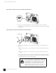
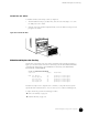
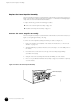
Figure 66: Attach Cables to a DC Power Supply
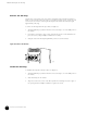
7. Secure the cable lugs to the terminal studs, first with locking washers, then nuts.
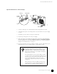
8. Verify that the DC power source wiring from the source DC breaker to the power supply
is correct.
9. Reinstall the protective shield covering the terminal studs.
10. Repeat Steps 4 through 9 for the other power supply.
11. Turn on the power to the management device that is connected to the Routing Engine
through the craft interface port labeled
CONSOLE, AUXILIARY, or MANAGEMENT ETHERNET.
For more information on connecting management devices, see “Connect the Router to
Management and Alarm Devices” on page 119.
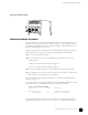
12. Press the power switch on the power supply to the
ON ( | ) position. Verify that the green
LED labeled
OK on the power supply faceplate eventually lights steadily.
.
1131
Grounding studs
Terminal studs
Input
Return
Cable lug
Locking
washers
Nuts
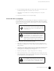
After a power supply is turned on, it can take up to 60
seconds for status indicators—such as LEDs on the power
supply,
show chassis commands, and messages on the
craft interface LCD—to indicate that the power supply is
functioning normally. Ignore error indicators that appear
during the first 60 seconds.
The Routing Engine boots as the power supply completes
its startup sequence. If the Routing Engine finishes booting
and you need to power down the router again, first issue
the CLI
request system halt command. For complete
instructions, see “Disconnect DC Power from the Router”
on page 147.
If after powering on the power supply you must power it
off, wait at least 60 seconds. After powering off a power
supply, wait 60 seconds before turning it back on.