Wireless LAN Access Point WLA522 and WLA522E Quick Start Guide Part Number: 530-042353 Rev.01 This guide provides basic hardware installation instructions for Juniper Networks WLA Series Indoor Wireless LAN Access Point (AP) WLA522 and WLA522E models.
Wireless LAN Access Point WLA522 and WLA522E Quick Start Guide Part Number: 530-042353 Rev.01 Warning: Attenzione! L’installazione deve essere effettuata unicamente da personale qualificato. Leggere e rispettare tutte le segnalazioni di attenzione e le istruzioni indicate sul prodotto o incluse nella documentazione. Prima d’installare il prodotto, leggere tutto il documento. Warning: ¡Advertencia! La instalación debe realizarse exclusivamente por parte de personal de servicio cualificado.
Wireless LAN Access Point WLA522 and WLA522E Quick Start Guide Part Number: 530-042353 Rev.01 Warning: 경고! 공인 서비스 기사만 설치 작업을 수행할 수 있습니다. 제품에 표시되어 있거나 설명서에 포함된 모든 경고 문구 및 지침을 읽어 보시고 준수하십시오. 제품을 설치하기 전에 본 설명서를 전체적으로 읽어 보시기 바랍니다.
Wireless LAN Access Point WLA522 and WLA522E Quick Start Guide Part Number: 530-042353 Rev.01 Installing and Connecting a WLA Informational Note: Before installing an AP, you might need to generate a network plan and an AP work order with RingMaster. (See RingMaster Network Plan and Work Orders below.) Installation Requirements and Recommendations For best results, follow these requirements and recommendations before installing a WLA.
Wireless LAN Access Point WLA522 and WLA522E Quick Start Guide Part Number: 530-042353 Rev.01 Radio Frequency Exposure Federal Communications Commission (FCC) Docket 96-8 for Spread Spectrum Transmitters specifies a safety standard for human exposure to radio frequency electromagnetic energy emitted by FCC-certified equipment. When used with Juniper-approved antennas, Juniper Networks APs meet the uncontrolled environmental limits found in OET-65 and ANSI C95.1-1991.
Wireless LAN Access Point WLA522 and WLA522E Quick Start Guide Part Number: 530-042353 Rev.01 Warning: FCC Notice for the WLA522E: For indoor operations: Devices will not permit operations on channels 120-132 for 11a and 11n/a which overlap the 5600 5650 MHz band.
Wireless LAN Access Point WLA522 and WLA522E Quick Start Guide Part Number: 530-042353 Rev.
Wireless LAN Access Point WLA522 and WLA522E Quick Start Guide Part Number: 530-042353 Rev.
Wireless LAN Access Point WLA522 and WLA522E Quick Start Guide Part Number: 530-042353 Rev.01 Additional Radio Safety Advisories Warning: In the U.S., locate the AP and any externally attached antennas a minimum of 50cm (19.7 inches) away from people. This safety warning conforms with FCC radio frequency exposure limits for dipole antennas such as those used in the AP.
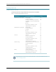
Wireless LAN Access Point WLA522 and WLA522E Quick Start Guide Part Number: 530-042353 Rev.01 Installing an Indoor AP Installation Hardware and Tools The table below lists the mounting hardware and tools required for AP installation. Table 2: Required Mounting Hardware and Tools Included with the Mounting Option Required Hardware and Tools Product Suspended ceiling—flush ceiling tiles Mounting template Yes Universal mounting bracket Yes T-bar clamp — A T-bar clamp is not required for a Yes 23.
Wireless LAN Access Point WLA522 and WLA522E Quick Start Guide Part Number: 530-042353 Rev.01 Installing an Indoor WLA522 Suspended Ceiling Installation — Flush Ceiling Tiles for the WLA522 1. Select an installation location centered over a T-bar in the ceiling. 2. Cut a hole as follows in the ceiling tile for the Cat 5 cable: 3. 4. a. Place the mounting template over the area where you plan to install the AP. b. Use the box cutter to cut along the line marking the opening for the port connectors.
Wireless LAN Access Point WLA522 and WLA522E Quick Start Guide Part Number: 530-042353 Rev.01 Figure 2: Step 5—Unlocking the Bracket 6. Remove the bracket as shown in Figure 3 below. Figure 3: Step 6—Removing the Bracket 7. Install the universal mounting bracket as follows onto the T-bar or T-bar clamp. a.
Wireless LAN Access Point WLA522 and WLA522E Quick Start Guide Part Number: 530-042353 Rev.01 Figure 4: Step 7—Top View Universal mounting bracket T-bar Port connector opening b. Properly align the bracket for mounting by placing the bracket so the port connector opening is to the left of the hole you cut for the cables. c. Rotate the universal mounting bracket clockwise until the flanges snap into place on the T-bar or clamp as shown in Figure 5 below.
Wireless LAN Access Point WLA522 and WLA522E Quick Start Guide Part Number: 530-042353 Rev.01 Informational Note: WLA522-Specific Optional Earthquake Safety Step At this point, once you have the T-bar installed and the universal mounting bracket snapped into place, you have the option of securing the bracket for earthquake safety using the two supplied M3 pan head threaded screws.
Wireless LAN Access Point WLA522 and WLA522E Quick Start Guide Part Number: 530-042353 Rev.01 a. Loop the Kensington lock cable around an object that cannot be moved or damaged by a person pulling on the cable. b. Insert the key into the Kensington lock. c. Insert the Kensington lock into the security slot on the AP. d. Rotate the key right or left to secure the lock to the AP. e. Pull on the lock to verify that it is secured to the AP. f. Remove the key. 11.
Wireless LAN Access Point WLA522 and WLA522E Quick Start Guide Part Number: 530-042353 Rev.01 Figure 7: Step 12—Locking the Bracket Lock 13. To ensure that the AP is fully locked onto the bracket, gently pull down on the AP and attempt to rotate it from side to side. 14. If the AP comes off the bracket, relock the device onto the bracket as described in step 12. 15. If the AP requires an external antenna, install and connect the antenna. Suspended Ceiling Installation—Drop Ceiling Tiles 1.
Wireless LAN Access Point WLA522 and WLA522E Quick Start Guide Part Number: 530-042353 Rev.01 Figure 8: Step 3—Installing the T-bar Clamp for a 23.9-millimeter (15/16-inch) T-bar T-bar Slide together T-bar clamp halves Figure 9: Step 3—Installing the T-bar Clamp for a 15.9-millimeter (5/8-inch) T-bar T-bar Slide together T-bar clamp halves 4.
Wireless LAN Access Point WLA522 and WLA522E Quick Start Guide Part Number: 530-042353 Rev.01 Figure 10: Step 4—Unlocking the Bracket 5. Remove the bracket as shown in Figure 11 below. Figure 11: Step 5—Removing the Bracket 6. 18 Install the universal mounting bracket as follows onto the T-bar clamp: a.
Wireless LAN Access Point WLA522 and WLA522E Quick Start Guide Part Number: 530-042353 Rev.01 Figure 12: Step 6—Top View Universal mounting bracket T- bar T-bar clamps (attached to T-bar) Port connector opening (Viewed from above ceiling tiles, looking down.) Figure 13: Step 6—Bottom View Port connector opening Universal mounting bracket T-bar 7.
Wireless LAN Access Point WLA522 and WLA522E Quick Start Guide Part Number: 530-042353 Rev.01 10. Lift the AP into place on the universal mounting bracket as shown in Figure 14. Make sure the cable feeds properly into the ceiling as you lift the device, and does not become trapped between the AP and the bracket. Figure 14: Step 9—Placing the AP on the Bracket 11. Lock the AP onto the bracket by inserting a small-pointed instrument or a paperclip into the Lock hole on the AP as shown in Figure 15 below.
Wireless LAN Access Point WLA522 and WLA522E Quick Start Guide Part Number: 530-042353 Rev.01 Junction Box Installation 1. Unlock the universal mounting bracket from the AP by inserting a small-pointed instrument or a paperclip into the Unlock hole on the AP as shown in Figure 16. Warning: Use a lock/unlock tool to unlock the AP. Do not use a screwdriver because it may cause damage to the AP lock mechanism or electronic components.
Wireless LAN Access Point WLA522 and WLA522E Quick Start Guide Part Number: 530-042353 Rev.01 Figure 18: Step 3—Placing the Bracket on the Junction Box Junction box Port connector opening 4. Pull the Cat 5 cable about 15 centimeters (about 6 inches) out of the junction box and through the port connector opening to create enough slack to insert the cable into the port connectors. 5. Insert the Cat 5 cable into the connector. 6. Install the Kensington lock, if you plan to use one. a.
Wireless LAN Access Point WLA522 and WLA522E Quick Start Guide Part Number: 530-042353 Rev.01 Figure 19: Step 7—Locking the Bracket Lock 9. To ensure that the AP is fully locked onto the bracket, gently pull down on the AP and attempt to rotate it from side to side. 10. If the AP comes off the bracket, relock the device onto the bracket. 11. If the AP requires an external antenna, install and connect the antenna.
Wireless LAN Access Point WLA522 and WLA522E Quick Start Guide Part Number: 530-042353 Rev.01 c. 3. Remove the screw from each anchor and save the screw(s) for step 6. Unlock the universal mounting bracket from the AP by inserting the lock/unlock tool into the Unlock hole on the AP as shown below. Caution: Use the lock/unlock tool to unlock the AP. Do not use a screwdriver because it may cause damage to the AP lock mechanism or electronic components.
Wireless LAN Access Point WLA522 and WLA522E Quick Start Guide Part Number: 530-042353 Rev.01 6. Insert the #6 sheet metal screws into the screw holes, and tighten them to secure the universal mounting bracket to the wall or ceiling. If you routed the Cat 5 cable through a hole in the wall or ceiling, insert the screw into the center screw hole only. Informational Note: Do not insert screws in the four holes on the edges of the bracket. The AP fits into these holes.
Wireless LAN Access Point WLA522 and WLA522E Quick Start Guide Part Number: 530-042353 Rev.01 Figure 23: Step 8—Cable Placement Cable Universal mounting bracket 10. Lock the AP onto the bracket by inserting the lock/unlock tool into the Lock hole on the AP as shown below. Warning: To prevent possible damage to the AP, make sure the device is fully locked onto the bracket before releasing it. Figure 24: Step 9—Locking the Bracket Lock 11.
Wireless LAN Access Point WLA522 and WLA522E Quick Start Guide Part Number: 530-042353 Rev.01 Tabletop Installation 1. Reverse the universal mounting bracket: a. Unlock the universal mounting bracket from the AP by inserting the lock/unlock tool into the Unlock hole on the AP as shown in Figure 25 below. Caution: Use the lock/unlock tool to unlock the AP. Do not use a screwdriver because it may cause damage to the AP lock mechanism or electronic components.
Wireless LAN Access Point WLA522 and WLA522E Quick Start Guide Part Number: 530-042353 Rev.01 Figure 27: Step 1c—Turning Over the Bracket d. Once the bracket is fully seated, lock the bracket onto the AP by inserting the lock/unlock tool into the Lock hole on the AP as shown in Figure 28 below. Figure 28: Step 1d—Locking the Bracket Lock 2. Insert the Cat 5 cable into the connector. 3. Install the Kensington lock, if you plan to use one. 4. 28 a.
Wireless LAN Access Point WLA522 and WLA522E Quick Start Guide Part Number: 530-042353 Rev.01 5. If the AP requires an external antenna, install and connect the antenna. Connecting an AP to an External Antenna Each radio on an Indoor AP can use an optional Juniper Networks external antenna. To mount the antenna, see the instructions that come with the antenna. To connect a mounted external antenna to an AP: 1.
Wireless LAN Access Point WLA522 and WLA522E Quick Start Guide Part Number: 530-042353 Rev.01 WLA522E Installation Antenna Orientation Adjust the WLA522E antennas as shown below for optimal polarization. Warning: Always turn the paddle antenna clockwise while adjusting the antenna orientation in order to prevent loosening of the connector.
Wireless LAN Access Point WLA522 and WLA522E Quick Start Guide Part Number: 530-042353 Rev.01 Connecting an AP to an WLC You can connect an AP directly to an WLC or indirectly to the WLC through an intermediate Layer 2 or Layer 3 network. If you are connecting the AP directly to an WLC, use the following procedure to insert the cable into the WLC and verify the link. You can use the CLI or RingMaster to configure an AP connection.
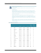
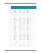
Wireless LAN Access Point WLA522 and WLA522E Quick Start Guide Part Number: 530-042353 Rev.01 Configuring the AP To configure the channels, power settings, and other AP parameters, see the following guide: Juniper Networks Mobility System Software Quick Start Guide External Antenna Connectors Table 3 below lists the Juniper Networks-supported WLA522E external antenna models.