Für Fachmann For den professionals Technical guide Gas condensing boiler SUPRAPUR Single boiler: KBR 120-3 A KBR 160-3 A KBR 200-3 A KBR 240-3 A KBR 280-3 A Cascade: MKB 240-3 MKB 320-3 MKB 400-3 MKB 480-3 MKB 560-3 A A A A A 6 720 645 817 (2010/09) Output range from 28 kW to 560 kW Wärme Leben Warmthfürs for life
Contents Contents 1 2 2 System schemes . . . . . . . . . . . . . . . . . . . . . . . . . 4 1.1 System scheme 1: unmixed heating circuit, low loss header . . . . . . . . . . . . . . 4 1.2 System scheme 2: unmixed underfloor heating circuit, low loss header . . . . . . . 6 1.3 System scheme 3: mixed heating circuit, DHW circuit, low loss header . . . 8 1.4 System scheme 4: one unmixed heating circuit, one mixed heating circuit, low loss header . . . . . . . . . . . . . . . . . . . 10 1.
Contents 7 8 9 Accessories / Services . . . . . . . . . . . . . . . . . . . 7.1 Neutralising systems . . . . . . . . . . . . . . . 7.1.1 Neutralising system no. 1605 . . . . . . . . . 7.1.2 Neutralising system no. 1606 . . . . . . . . . 7.1.3 Condensate lifting system no. 1620 . . . 7.2 Pumps . . . . . . . . . . . . . . . . . . . . . . . . . . 7.3 Dirt traps . . . . . . . . . . . . . . . . . . . . . . . . 7.4 Low loss header . . . . . . . . . . . . . . . . . . . 7.5 Boiler safety set . . . . . . . . . .
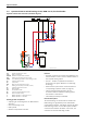
System schemes 1 System schemes 1.1 System scheme 1: unmixed heating circuit, low loss header Hydraulic scheme with controller (schematic diagram) FW 100 3 CUx IPM 1 1 T 3 T P VF HP AF Suprapur KBR 120-280 6 720 643 417-02.1O Fig.
System schemes The controller is suitable for wall mounting inside the boiler room or in the living space. Installing it in the living space enables room temperature hook-up. Parts list Model code Description Part no.
System schemes 1.2 System scheme 2: unmixed underfloor heating circuit, low loss header Hydraulic scheme with controller (schematic diagram) FW 100 3 CUx IPM 1 1 3 TB T T P VF AF HP Suprapur KBR 120-280 6 720 643 417-01.1O Fig.
System schemes Parts list Model code Description Part no.
System schemes 1.3 System scheme 3: mixed heating circuit, DHW circuit, low loss header Hydraulic scheme with controller (schematic diagram) FW 100 3 CUx IPM 2 1 3 TB MF T LP VF HP T M P M AF ZP SF ST ... Suprapur KBR 120-280 6 720 643 417-03.1O Fig.
System schemes The controller is suitable for wall mounting inside the boiler room or in the living space. Installing it in the living space enables room temperature hook-up. Parts list Model code Description Part no.
System schemes 1.4 System scheme 4: one unmixed heating circuit, one mixed heating circuit, low loss header Hydraulic scheme with controller (schematic diagram) FW 200 3 CUx IPM 2 1 3 TB MF T T T T P1 M VF HP P2 M AF Suprapur KBR 120-280 6 720 643 417-04.1O Fig.
System schemes The controller is suitable for wall mounting inside the boiler room or in the living space. Installing it in the living space enables room temperature hook-up. Parts list Model code Description Part no.
System schemes 1.5 System scheme 5: two mixed heating circuits, one DHW circuit, low loss header Hydraulic scheme with controller (schematic diagram) FW 200 3 CUx IPM 1 1 IPM 2 3 3 TB1 MF1 T LP VF HP T TB2 MF2 T M P1 M1 T M P2 M2 AF ZP SF ST ... Suprapur KBR 120-280 6 720 643 417-06.1O Fig. 5 AF CUx FW 200 HP IPM 1 IPM 2 LP M1,2 MF1,2 P1,2 SF ST ...
System schemes The controller is suitable for wall mounting inside the boiler room or in the living space. Installing it in the living space enables room temperature hook-up. Parts list Model code Description Part no.
System schemes 1.6 System scheme 6: one unmixed heating circuit, two mixed heating circuits, low loss header Hydraulic scheme with controller (schematic diagram) CUx FW 200 3 IPM 2 1 IPM 1 3 T T T T P1 M VK HP P2 M2 FB 100 3 TB MF3 TB MF2 T 3 T M P3 M3 AF Suprapur KBR 120-280 6 720 643 417-07.1O Fig.
System schemes The controller is suitable for wall mounting inside the boiler room or in the living space. Installing it in the living space enables room temperature hook-up. A FB 100 remote control is required for the third heating circuit. Parts list Model code Description Part no.
System schemes 1.7 System scheme 7: one unmixed heating circuit, three mixed heating circuits, low loss header Hydraulic scheme with controller (schematic diagram) FW 200 3 CUx IPM 2 1 FB 100 IPM 2 FB 100 3 3 3 3 TB MF3 TB MF2 T T T T T P1 M VF P2 M2 T TB MF4 T M P3 M3 T M P4 M4 AF HP Suprapur KBR 120-280 6 720 643 417-08.1O Fig.
System schemes The controller is suitable for wall mounting inside the boiler room or in the living space. Installing it in the living space enables room temperature hook-up. One FB 100 remote control is required for each of the third and fourth heating circuits. Parts list Model code Description Part no.
System schemes 1.8 System scheme 8: two mixed heating circuits, two DHW circuits, low loss header Hydraulic scheme with controller (schematic diagram) FW 500 3 CUx IPM 2 1 IPM 2 3 3 TB MF1 T LP1 VF HP ZP T LP2 TB MF2 T M P1 M1 T M P2 M2 AF ZP SF ST ... SF ST ... Suprapur KBR 120-280 6 720 643 417-09.1O Fig. 8 AF CUx FW 500 HP IPM 2 LP1,2 M1,2 MF1,2 P1,2 SF ST ...
System schemes Function description The heating circuits are regulated by an FW 500 weather-compensated controller. This always requires two IPM 2 load switching modules. A 2-wire BUS system enables communication between the boiler control unit, the controller and the load switching modules. The controller is suitable for wall mounting inside the boiler room or in the living space. Installing it in the living space enables room temperature hook-up. Parts list Model code Description Part no.
System schemes 1.9 System scheme 9: one unmixed heating circuit, one DHW circuit, low loss header, cascade Hydraulic scheme with controller (schematic diagram) FW 200 3 CUx 1 ICM IPM 2 3 CUx 3 1 AF T T P LP VF HP HP ZP SF ST ... Suprapur MKB 240-560 6 720 643 417-10.1O Fig. 9 AF CUx FW 200 HP ICM IPM 2 LP P SF ST ...
System schemes The controller is suitable for wall mounting inside the boiler room or in the living space. Installing it in the living space enables room temperature hook-up. Parts list Model code Description Part no.
Specification 2 Specification 2.1 Appliance parameters 2.1.1 Single appliance Suprapur KBR ... Boiler size (output in kW) Number of sections Unit KBR 120-3 A KBR 160-3 A KBR 200-3 A KBR 200-3 A KBR 240-3 A – 4 5 6 7 8 Rated output full load/partial load temperature pair 50/30 °C kW 120/31 160/42 200/62 240/75 280/87 Rated output full load/partial load temperature pair 80/60 °C kW 113/28 150/38 187/56.2 225/67.6 263/79.2 Rated heat input full load/partial load kW 115.
Specification 2.1.2 Factory-prepared cascade Suprapur MKB ... Boiler size (output in kW) Number of sections Unit MKB 240-3 A MKB 320-3 A MKB 400-3 A MKB 480-3 A MKB 560-3 A – 8 10 12 14 16 Rated output full load/partial load temperature pair 50/30 °C kW 240/31 320/42 400/62 480/75 560/87 Rated output full load/partial load temperature pair 80/60 °C kW 226/28 300/38 374/56.2 450/67.6 526/79.2 Rated heat input full load/partial load kW 232/29 310/38.8 386/57.9 464/69.
Specification 2.2 Dimensions and minimum clearances 2.2.1 Single appliance Suprapur KBR ... XGAS, XAL, XRK 176 680 1515 1400 VK GAS ZAA 1143 1018 AL YVK 1) 615 RK AA F ØAA 34 YAA YMAG 15 - 25 MAG 182 100 AKO 496 XAA 1) SV 120 176 B 6 720 643 417-24.1O Fig. 10 Suprapur KBR 120 ...
Specification 2.2.2 Factory-prepared 2-boiler cascade MKB ... 215 500 YVK ØAA R YAA VK XGAS, XAL 1143 XAA GAS 1018 1517 AL U 615 RK 1) YRK K N M BG BK S 717 O TZ TG 1) 1) 6 720 643 417-13.1O Fig.
Specification Unit MKB 240-3 A MKB 320-3 A MKB 400-3 A MKB 480-3 A MKB 560-3 A BK mm 994 1202 1202 1410 1410 BG mm 2041 2243 2421 2620 2573 TG mm 1842 1995 2135 2139 2135 TZ mm 640 795 935 939 935 – DN 200 DN 200 DN 250 DN 250 DN 250 YAA mm 1335 1342 2126 2135 2130 XAA mm 332 384 436 488 540 Ø VK – DN 65 DN 80 DN 80 DN 100 DN 100 mm 1308 1299 1299 1299 1299 – DN 65 DN 80 DN 80 DN 100 DN 100 YRK mm 339.
Specification 2.3 Installed dimensions Wherever possible, site the Suprapur gas condensing boiler with the recommended wall clearances (Æ Fig. 12). This ensures good accessibility for installation, maintenance and service. Single appliance Suprapur KBR ... B 2.3.1 A reduction of the minimum clearances makes boiler access more difficult. D A C 6 720 644 748-07.1O Fig.
Specification Factory-prepared cascade MKB ... A 2.3.2 C 800 ≥ 100 S A B 6 720 644 748-09.1O Fig. 13 Installed dimensions Suprapur factory-prepared 2-boiler cascade (dim. in mm) Unit MKB 240-3 A MKB 320-3 A MKB 400-3 A MKB 480-3 A MKB 560-3 A A mm 700/500 700/500 700/500 700/500 700/500 B mm –/900 –/850 –/1000 –/940 –/890 C1) mm –/1320 –/1370 –/1370 –/1420 –/1420 S mm –/419 –/367 –/515 –/454 –/407 Tab.
Specification 2.4 Pressure drop, water side The pressure drop on the water side is the pressure differential between the boiler flow and return connections of the gas condensing boiler. It depends on the boiler size and the heating water flow rate. Fig. 14 Pressure drop on the heating water side without check valve x y Flow rate in l/h Pressure drop on the heating water side in mbar Fig.
Specification 2.5 Boiler efficiency 2.6 The boiler efficiency ηK identifies the ratio of heat output to heat input subject to the return temperature. ηK [%] 108 106 104 Standby loss The standby loss qB is part of the rated heat input that is required to achieve the specified boiler water temperature. The cause of this loss is the cooling down of the boiler through radiation and convection during the standby time (burner idle time).
Specification 2.7 Flue gas temperature 2.8 The flue gas temperature ϑA is the temperature captured inside the flue pipe, specifically at the boiler flue outlet. It depends on the return temperature. ϑA [°C] 80 Conversion factor for alternative system temperatures In the tables containing the technical details of the Suprapur gas condensing boilers, the rated output figures relate to system temperatures 50/30 °C and 80/60 °C.
Appliance layout 3 Appliance layout Fig.
Product description 4 Product description 4.1 Gas condensing boiler with aluminium heat exchanger 4.1.1 1 7 2 6 The Suprapur gas condensing boiler is available as a single boiler with output ranging from 120 kW to 280 kW and as a factory-prepared cascade with output from 240 kW to 560 kW. 4.1.2 3 4 Possible applications The Suprapur gas condensing boiler is suitable for all heating systems compliant with DIN-EN 12828.
Product description 4.2 Gas burner Advanced boiler concept 4.2.1 Burner and burner control unit • Heat exchanger made from high grade aluminium-silicon sand casting A highly premixing modulating gas premix burner with clean combustion is used in the Suprapur gas condensing boiler. The gas burner comprises a fan, gas valve and, subject to boiler size, several burner rods. 4.1.
Product description 4.2.2 Burner function The maximum ΔT between flow and return temperature at rated output is 30 K. From ΔT = 30 K, when no heat is being drawn off, the burner modulates the boiler output down to the lowest output. The boiler shuts down only if ΔT continues to rise and exceeds 40 K. If ΔT is too high, the boiler cannot transfer its maximum output due to its safety circuit.
Engineering information and sizing the heat source 5 Engineering information and sizing the heat source 5.1 Operating conditions Tab. 18 provides an overview of the conditions that must be observed, subject to the application and the local system-specific circumstances. Δϑmax Minimum Max.
Engineering information and sizing the heat source Limit curves V / m3 280 kW 7 240 kW 6 200 kW 5 A 160 kW 4 120 kW 3 2 1 B 0 0 5 10 15 20 25 30 HW / °dH 6 720 643 417-14.1O Fig. 22 Limit curves for water treatment – single boiler V / m3 16 560 kW 14 480 kW 12 400 kW 10 A 320 kW 8 240 kW 6 4 2 B 0 0 5 10 15 6 720 643 417-15.1O 20 25 30 HW / °dH Fig. 23 Limit curves for water treatment – factory-prepared 2-boiler cascade Key to Fig. 22 and Fig.
Engineering information and sizing the heat source Water treatment measures Estimate of system capacity There are two methods for treating the fill and top-up water for Suprapur gas condensing boilers: Especially with older systems, the water capacity of the entire system is often not known. The following graph gives an estimate of the system capacity.
Engineering information and sizing the heat source 5.3 Important hydraulic system components 5.3.1 Hydraulics for maximum utilisation of the condensing effect Always use the Suprapur gas condensing boilers with a low loss header. For systems where the heating circuits are connected via a low loss header, we recommend that the pump is controlled subject to boiler output. This operating principle enables the system to operate with maximum utilisation of the condensing effect. 5.3.
Engineering information and sizing the heat source Example 2 Given n Flow temperature (Æ table 19): ϑV = 50 °C o MAG pre-charge pressure (Æ table 19): p0 = 1.00 bar from example 1: system volume: VA = 4000 l Actual p A MAG with 200 l capacity is required (Æ table 19), as the system volume determined in accordance with Fig. 25 is smaller than the maximum permissible system volume.
Engineering information and sizing the heat source 5.4 Condensate drainage Materials for condensate lines Route the condensate from condensing boilers correctly into the public sewage system. It is essential to determine whether the condensate must be neutralised prior to discharge into the sewer system. This depends on the boiler output and the relevant regulations of the local water authority (Æ table 20).
Engineering information and sizing the heat source 5.4.1 Condensate drain from the condensing boiler and the flue To ensure the condensate created in the flue can drain via the condensing boiler, route the flue inside the installation room with a slight fall (≥ 3°, i.e. approx. 5 cm height differential per metre) towards the gas condensing boiler. Observe all relevant regulations concerning the building's drains, as well as local regulations.
Regulations and operating conditions 6 Regulations and operating conditions 6.1 Extracts from regulations Inspection/maintenance The Suprapur gas condensing boilers meet the requirements of DIN-EN 677, the EC Efficiency Directive, the Gas Appliances Directive and the EMC/LV Directive. Keep the system in good order and clean it regularly (recommendation: every two years). The entire system should be checked annually for perfect function.
Regulations and operating conditions 6.4 Combustion air Where combustion air is concerned, ensure that it is not heavily contaminated with dust and contains no halogenated compounds. Otherwise there would be a risk of damage to the combustion chamber and the secondary heating surfaces. Halogenated compounds are highly corrosive. These can be contained in spray cans, thinners, cleaning & degreasing agents and solvents.
Regulations and operating conditions 6.6 Siting combustion equipment Subject to the regulations of the relevant country, gas combustion equipment with a total rated output in excess of 50 kW may only be installed in rooms: • that are not used for any other purpose • that have no opening towards other rooms, except doors • the doors of which are tight and self-closing or • that can be ventilated.
Accessories / Services 7 Accessories / Services 7.1 Neutralising systems Neutralising systems no. 1605 and no. 1606 can be used if the condensate needs to be neutralised. Install these between the condensate outlet from the gas condensing boiler and the connection to the public sewer system. Site the neutralising system behind or adjacent to the gas condensing boiler. The neutralising systems no. 1605 and no. 1606 can be integrated in the Suprapur condensing boilers.
Accessories / Services 7.1.2 Neutralising system no. 1606 7.1.3 The neutralising system no. 1606 comprises a plastic casing with a chamber to hold the neutralising granulate, a back-up area for the neutralised condensate and a level-controlled condensate pump with a head of approx. 2.0 m. No. 1606 enables the neutralisation of condensate volumes from systems with up to approx. 850 kW rated output. The neutralising system no. 1606 is equipped with a stand-alone 230 V power supply.
Accessories / Services 7.3 7 H/m Deposits in heating systems can lead to local overheating, noise and corrosion. Any resulting boiler damage falls outside the warranty obligations. 6 5 4 To remove dirt deposits, flush the new heating system thoroughly prior to installing and commissioning a boiler. In addition, we recommend the installation of dirt traps or a blow-down facility. 3 2 1 0 0 50 100 150 . V / l/min 200 250 300 350 400 6 720 619 379-56.1O Fig. 30 Residual head no. 1620 H .
Accessories / Services The maximum flow temperature drops through mixing to a lower temperature level in the low loss header. 7.6 Safety equipment to DIN-EN 12828 As standard, the Suprapur KBR ... is equipped with a low water indicator (minimum pressure switch) and boiler drain & fill valve. ΔT on ΔT on Max. flow Max.
Accessories / Services 7.7 Shut-off set combined with check valve 2 1 3 2 4 2 5 7.9 Ventilation air connection bend A connection bend for balanced flue operation is available in translucent PP for the Suprapur KBR ... The connection bend DN 110 has an angle of 90° and a test port. Adaptors are available for larger dimensions. 7.10 Cleaning tool A special cleaning tool is available for the Suprapur KBR ... VK 6 720 642 877-17.1il Fig.
Heating controls 8 Heating controls A control unit is required to operate gas condensing boilers. The Junkers control systems are of modular design. This enables the system to be matched inexpensively to the individual application and equipment installed in the planned heating system. 8.1 Selection aids for controller application The Suprapur gas condensing boilers are factory-fitted with a BUS-enabled boiler control unit and without a separate controller.
Heating controls 8.
Heating controls 8.
Heating controls FW 200 Application • Weather-compensated flow temperature controller • Constant output control • Communication with the condensing boiler via 2-wire BUS Function • 2-wire BUS technology, reverse polarity protected connection • Controls two mixed heating circuits without remote control • Up to four mixed heating circuits possible (FW 200 + FB 100 + two IPM 2) • DHW program for DHW cylinder (adjustable time and temperature) • Solar DHW heating (with ISM 1) • Solar central heating backup (wi
Heating controls FW 500 Application • Weather-compensated flow temperature controller • Constant output control • Communication with the condensing boiler via 2-wire BUS Function • 2-wire BUS technology, reverse polarity protected connection • Controls two mixed heating circuits without remote control • Up to 10 mixed heating circuits possible (FW 500 + eight FB 100 + five IPM 2) • DHW program for DHW cylinder (adjustable time and temperature) • Solar DHW heating (with ISM 1) • Solar central heating backu
Heating controls 8.4 IPM 1 Accessory for 2-wire BUS controller Application • Load switching module for switching a heating circuit pump and mixer for one mixed or unmixed heating circuit or • Switching the cylinder primary pump and DHW circulation pump for one cylinder circuit • Communication with the condensing boiler and controller via 2-wire BUS • Sensor inputs for – 1 external flow temperature sensor, e.g.
Heating controls ISM 1 Application • Solar module for solar DHW heating in conjunction with Fx controller • Communication with the condensing boiler and controller via 2-wire BUS • 3 switching outputs 230 V AC, 50 Hz, 2.5 A, max. 80 W • 3 sensor inputs • Function status LED Installation • Top-hat profile rail installation or wall mounting (height/width/depth: 110/156/55 mm) • Power supply 230 V AC, 50 Hz, 2.
Heating controls 8.
Heating controls FB 100 Application • Remote control for weather-compensated operation with room temperature hook-up in conjunction with FW 100 or FW 200 • May be used for heating circuits 3 and 4 of the FW 200 controller • Communication with the controller via 2-wire BUS Function • 2-wire BUS technology, reverse polarity protected connection • Optional solar optimisation for the heating circuit • Display of date and time (synchronised via BUS system) in plain text • Plain text display of fault messages •
DHW heating 9 DHW heating 9.1 General DHW heating is only possible via an indirectly heated DHW cylinder. This must be integrated downstream of the low loss header. Selecting DHW cylinders Junkers KBR 120-280-3 A gas condensing boilers can be combined with the following cylinder models from the Junkers DHW cylinder range: • SK 300/400/500-3 ZB The DHW cylinders SK 300... - SK 1000... are equipped with an enamelled smooth tube internal indirect coil.
DHW heating DHW convenience The performance factor to DIN 4108 corresponds to the number of residential units to be supplied, each with 3.5 occupants, one standard bath tub and two further draw-off points. Larger bath tubs may require a higher NL factor; fewer occupants may require a lower one. cold water safety assemblies are available from the Junkers range of accessories. Provide the cold water safety assembly on site for larger DHW cylinders. Min. Max.
DHW heating Cylinder connection on the heating side The sizing of the connection lines for the cylinder flow and return is based on a temperature differential of 20 K. Table 35 shows the resulting internal diameters. When using flexible connection lines, such as corrugated stainless steel hoses, apply a higher pressure drop than for rigid pipework.
DHW heating DHW circulation line Parallel connection of two cylinders Junkers cylinders must be equipped with their own DHW circulation connection. WW SV Seal this connection if no DHW circulation line is connected. AV AV SV RSP DHW circulation is only permitted with reference to the cool-down losses if a time- and/or temperaturedependent DHW circulation pump is provided. VSP Install a suitable non-return valve. S S S S RV ZP S S MS RV DM AV S S E Z E KW PV 6 720 604 132-15.
DHW heating DHW expansion vessel Overheating/flow limitation Installing an expansion vessel that is suitable for drinking water can prevent unnecessary water loss. Install it in the cold water supply line between the cylinder and the safety assembly. The expansion vessel must receive a DHW flow with every DHW drawing. Junkers DHW cylinders are optimised for maximum output (NL factor).
DHW heating 9.2 DHW cylinders series SK ... Installation and connection dimensions SK 300/400/500-3 ZB 35 > = 300 WW L R 1 1 /4 55 30 710 SK 300 = 1290 SK 400 = 1646 SK 500 = 1966 768 / 1124 / 1683 937 / 1037 / 1287 MA SK500 837 / 937 / 1187 T1 219 > = 1000 SE 8 MA SK300/400 1227 / 1583 / 1903 T Z R SP R 3 /4 R 1 1 /4 V SP R 1 1 /4 KW/E R 1 1 /4 4132-33.1R Fig.
DHW heating Installation and connection dimensions SK 800/1000-ZB Ø 920 / Ø 1040 EL Rp 1 T WW R 1¼ / R 1½ ≥ 1000 ZL Rp ¾ RSP Rp 1½ SF MA R 1½ 455 / 465 KW 350 / 360 500 / 510 VSP Rp 1½ Ø 270 Ø 180 L 1345 1245 / 1255 1835 / 1770 2180 / 2170 MA E Rp 1 6 720 640 088-01.2O Fig. 40 Connection point for on-site draining Rp 1 (fem. thread) Connection point for on-site air vent valve Rp 1 (fem.
DHW heating Pressure drop of the indirect coil SK 800/1000-ZB Pipework-related pressure drop values have not been taken into account in the graphs. Dp (bar) 0,4 0,3 0,2 SK 300/400/500-3 ZB Δp / bar 0,1 0,4 0,08 0,3 0,06 0,05 0,04 10 00 0,03 0,2 SK 80 0/ 0,02 0,01 0,1 0,008 0,08 1 0,006 0,005 0,06 0,05 0,004 0,003 2 0,04 0,002 0,03 3 0,001 0,02 0,2 0,4 0,6 0,8 1,0 2,0 3,0 4,0 4132-05.2R 6,0 8,0 V (m /h) 3 Fig.
DHW heating Specification Cylinder type Unit SK 300-3 ZB SK 400-3 ZB SK 500-3 ZB SK 800 ZB SK 1000-ZB Heat exchanger Heat transfer – Indirect coil Indirect coil Indirect coil Indirect coil Indirect coil Number of coils – 10 13 17 32 32 Available capacity l 293 388 470 760 950 Heating water content l 10 12 14 36.1 42.1 m2 1.5 1.8 2.6 5.7 6.7 – 8.7 13.5 17 35 45 l l 365 426 482 563 584 682 1010 1178 1262 1473 kWh/d 2.2 2.5 3.1 4.6 4.8 Max.
DHW heating 9.3 DHW cylinders series SE ... T ≥ 200 Installation and connection dimensions SE 300-1 RSP WW ZL KW VSP R1 R1 R¾ R1 R1 333 278 1795 Ø 660 348 105 105 105 105 177 T1 6 720 643 417-28.1O Fig.
DHW heating Pressure drop of the indirect coil Δp / bar 0,4 0,3 0,2 0,1 0,08 0,06 0,05 0,04 0,03 0,02 0,01 0,6 0,8 1,0 6 720 615 094-02.2O 2,0 3,0 4,0 5,0 V / m3/h Fig. 45 Pressure drop of the indirect coil in bar Δp V Pressure drop Flow rate Pressure drop through the network has not been taken into account on this graph.
DHW heating Specification Cylinder type Unit SE 300-1 Heat transfer – Indirect coil Number of coils – – Available capacity l 288 Heating water content l – m2 0.93 – 11.5 l l 441 – kWh/d 1.92 Maximum operating pressure, water bar 10 Maximum operating pressure, heating bar 15 Weight (empty, excl. packaging) kg 50 – White Heat exchanger Heating surface Performance factor NL1) to DIN 4708 at max.
Installation accessories 10 Installation accessories 10.1 Connection accessories Designation/accessory no. Part no. No. 1600 8 718 576 603 Boiler safety assembly G 1½ With diaphragm safety valve ¾", 3 bar No. 1601 8 718 576 606 Heating circuit connection set G 1½ angled version For heating circuit flow and return, with shut-off valves No. 1602 8 718 576 604 Heating circuit connection set G 1½ straight-through version For heating circuit flow and return, with shut-off valves No.
Installation accessories Designation/accessory no. Part no. No. 885 7 719 002 146 Waste set incl. fixing parts and drain hose for safety valve TB 1 7 719 002 255 Temperature limiter for underfloor heating system Contact thermostat with gold contacts, setting range 30 ... 60 °C Tab. 40 10.2 Cascade accessories Designation/accessory no. Part no. Hydraulic shut-off set No. 1644 for MKB 240-3 A 7 747 301 092 No. 1645 for MKB 320-3 A 7 747 301 093 No. 1646 for MKB 400 ...
Installation accessories 10.3 Other accessories Designation/accessory no. Part no. No. 1620 80 695 080 Condensate pump Without neutralising system; max. head 6 m No. 1605 8 718 576 749 Neutralising tank Incl. granulate filling, connection components, inlet and drain hoses No. 1606 8 718 577 421 Neutralising tank with integral level-controlled condensate pump, 2 m head Incl. granulate filling Neutralising granulate 7 115 120 Refill pack Tab.
Flue systems 11 Flue systems 11.1 Flue system 11.1.1 Requirements Standards, regulations and directives Flues must be resistant to moisture, flue gas and corrosive condensate. They must comply with the applicable technical rules and local regulations. General information • Use only flues that conform to building regulations. • Observe the requirements in the approval notice. • Size the flue system correctly (essential for correct function and safe boiler operation).
Flue systems 11.1.2 Plastic flue system Chimney shaft requirements Matching flue systems for these gas condensing boilers are available for positive pressure operation, i.e. DN 125, DN 160, DN 200 and DN 250. These flue systems are made from translucent polypropylene. They have building regulation approval [Germany] for flue gas temperatures up to 120 °C. All systems are supplied ready to plug in; no welding is required.
Flue systems 11.1.3 Flue gas parameters Suprapur – single boiler KBR ... Rated output System Boiler temperature size 50/30 °C 80/60 °C Rated heat input Flue outlet Full load Partial load Full load Partial load [kW] [kW] [kW] [kW] [mm] 120 120 31 116 29 160 160 42 155 38.
Flue systems 11.2 Flue systems for open flue operation 11.2.1 General information for open flue operation Regulations In accordance with the DVGW-TRGI 2008 technical rules [Germany] governing gas installations, the contracted installer must seek the agreement of the responsible flue gas inspector prior to commencing work on the flue system or notify the flue gas inspector of the installation in writing. In this connection, observe the relevant national and regional regulations.
Flue systems 11.2.2 Ventilation air/flue gas line Junkers sets The flue that is part of the Junkers set is made from plastic. It is installed as a complete pipe system or as a connection piece between the gas condensing boiler and a moisture-resistant chimney. L Combustion air supply In open flue mode, the fan of the gas condensing boiler draws the required combustion air from the installation room.
Flue systems 11.2.3 Open flue routing via flue inside a chimney shaft (B23) 2 3 4 1 5 L 3 4 1 1 9 8 5 5 6 9 7 6 720 643 417-30.1O Fig. 48 Key Æ Tab.
Flue systems Flue accessories Ø 125 mm (Æ page 92 ff.) Boiler flue connection, 87° bend AZB 1350 Boiler flue connection, straight AZB 1352 Chimney shaft set Chimney shaft cover Terminal pipe Spacer Extension pipe 0.
Flue systems Bend Equivalent pipe length 90° 2m 15° - 45° 1m Tab. 48 Equivalent pipe lengths of bends 11.2.4 Balanced flue routing, vertical via the roof (B23) 1 1 2 L 7 3 4 5 6 6 720 643 417-31.1O Fig. 49 Key Æ Tab.
Flue systems Flue accessories Ø 125 mm (Æ page 92 ff.) Ø 160 mm (Æ page 97 ff.) Boiler flue connection, 87° bend AZB 1350 AZB 1350 AZB 1351 AZB 1351 AZB 1351 Boiler flue connection, straight AZB 1352 AZB 1352 AZB 1353 AZB 1353 AZB 1353 1 Vertical flue gas routing AZB 1323 AZB 1324 AZB 1325 AZB 1326 2 Universal roof tile AZB 923 AZB 925 AZB 1320 AZB 1321 – – 2 Roof tile, special – – AZB 1341 AZB 1342 3 Extension pipe 0.
Flue systems 11.2.5 Open flue routing via flue over a facade (B23) 2 3 4 L 1 4 3 8 6 5 7 6 720 643 417-32.1O Fig. 50 Key Æ Tab.
Flue systems Flue accessories Ø 125 mm (Æ page 92 ff.) Boiler flue connection, 87° bend AZB 1350 Boiler flue connection, straight AZB 1352 Facade pack Terminal piece Terminal pipe Clamping strap Roof outlet, facade AZB 1331 AZB 1358 AZB 1049 AZB 1056 AZB 1027 AZB 923 AZB 925 – AZ 136 AZB 1045 AZB 1001 AZB 1005 Ø 160 mm (Æ page 97 ff.
Flue systems 11.3 Flue systems for balanced flue operation 11.3.1 General information for balanced flue operation Regulations In accordance with the DVGW-TRGI 2008 technical rules [Germany] governing gas installations, the contracted installer must seek the agreement of the responsible flue gas inspector prior to commencing work on the flue system or notify the flue gas inspector of the installation in writing. In this connection, observe the relevant national and regional regulations.
Flue systems Ventilation air/flue gas line Junkers sets In balanced flue operation, the fan draws in the required combustion air from the outside into the gas condensing boiler. The ventilation air and flue lines are routed in parallel. The balanced flue sets have not been system certified. A calculation to DIN-EN 13384 is required. This can be performed by Junkers.
Flue systems 11.3.2 Balanced flue routing via flue inside a chimney shaft whilst drawing in combustion air in countercurrent (C93) 2 3 4 1 5 L 3 4 1 1 8 7 5 5 6 4 8 6 720 643 417-33.1O Fig. 52 Key Æ Tab.
Flue systems Flue accessories Ø 125 mm (Æ page 92 ff.) Ø 160 mm (Æ page 97 ff.) Boiler flue connection, 87° bend AZB 1350 AZB 1350 AZB 1351 AZB 1351 AZB 1351 Boiler flue connection, straight AZB 1352 AZB 1352 AZB 1353 AZB 1353 AZB 1353 1 Chimney shaft set AZB 702/1 AZB 953 AZB 954 AZB 955 2 Chimney shaft cover AZB 1308 AZB 1309 AZB 1310 AZB 1311 Description Ø 200 mm Ø 250 mm (Æ page 103 ff.) (Æ page 109 ff.
Flue systems 11.3.3 Balanced flue routing via flue inside a chimney shaft whilst drawing in combustion air through a separate pipe (C53) 2 3 4 1 5 L 3 4 1 1 9 8 5 6 5 9 4 7 6 720 643 417-34.1O Fig. 53 Key Æ Tab.
Flue systems Flue accessories Ø 125 mm (Æ page 92 ff.) Ø 160 mm (Æ page 97 ff.) Boiler flue connection, 87° bend AZB 1350 AZB 1350 AZB 1351 AZB 1351 AZB 1351 Boiler flue connection, straight AZB 1352 AZB 1352 AZB 1353 AZB 1353 AZB 1353 1 Chimney shaft set AZB 702/1 AZB 953 AZB 954 AZB 955 2 Chimney shaft cover AZB 1308 AZB 1309 AZB 1310 AZB 1311 Description Ø 200 mm Ø 250 mm (Æ page 103 ff.) (Æ page 109 ff.
Flue systems 11.4 Visual overview of flue accessories 11.4.
Flue systems Standard delivery Designation/description Part number AZB 724/1 7 719 002 895 30° bend, flue side, Ø 125 mm, made from PP AZB 719/1 7 719 002 894 15° bend, flue side, Ø 125 mm, made from PP AZB 1300 87 094 780 Enlargement adaptor for ventilation air connection from Ø 110 mm to Ø 125 mm, made from PP for KBR 120 ... 280-3 A for balanced flue operation AZB 1301 87 094 782 Enlargement adaptor for ventilation air connection from Ø 110 mm to Ø 160 mm, made from PP for KBR 120 ...
Flue systems Standard delivery Designation/description Part number AZB 925 7 719 002 857 Universal roof tile, Ø 125 mm, black for roof pitch 25° - 45° AZ 136 7 719 000 838 Flat roof flange, Ø 125 mm Tab.
Flue systems Standard delivery Designation/description Part number AZB 713/1 7 719 002 898 Spacer for flue inside chimney shaft, Ø 125 mm AZB 1308 87 090 762 Chimney shaft cover, Ø 125 mm, made from stainless steel with terminal pipe made from PP AZB 1049 7 746 900 998 Terminal pipe, Ø 125 mm, made from stainless steel for optional replacement of terminal pipe made from PP AZB 1052 7 746 901 001 Installation aid, pipe clip with eyelets for pipes with Ø 125 mm Tab.
Flue systems Special flue accessories for routing the flue on a facade Standard delivery Designation/description Part number AZB 1331 87 090 951 Facade pack Ø 125 mm, stainless steel with support bend and panel AZB 1001, AZB 1005 Extension pipe for facade solution, Ø 125/185 mm, made from stainless steel/PP AZB 1001: AZB 1005: L = 500 mm L = 1000 mm AZB 1023 7 746 900 721 7 746 900 725 7 746 900 986 Inspection aperture for facade solution, Ø 125/185 mm, made from stainless steel/PP AZB 1015 7 7
Flue systems Standard delivery Designation/description Part number AZB 1027 7 746 900 990 Roof outlet for facade solution, Ø 125/185 mm, made from stainless steel/PP AZB 1358 87 090 971 Terminal piece, Ø 125/185 mm, made from stainless steel/PP with clamping strap AZB 1049 7 746 900 998 Terminal pipe, Ø 125 mm, made from stainless steel for optional replacement of terminal pipe made from PP AZB 1056 7 746 901 005 Clamping strap, Ø 185 mm Tab. 62 11.4.
Flue systems Standard delivery Designation/description Part number AZB 1351 7 747 003 466 Boiler flue connection with test port, 87° bend Ø 200 mm for KBR 200/240/280-3 A AZB 1353 7 747 003 468 Boiler flue connection with test port, straight Ø 200 mm for KBR 200/240/280-3 A AZB 978, AZB 982, AZB 986 Extension pipe, flue side, Ø 160 mm, made from PP AZB 978: AZB 982: AZB 986: L = 500 mm L = 1000 mm L = 2000 mm AZB 994 7 746 900 698 7 746 900 702 7 746 900 706 7 746 900 714 Inspection aperture,
Flue systems Standard delivery Designation/description Part number AZB 966 7 746 900 686 30° bend, flue side, Ø 160 mm, made from PP AZB 964 7 746 900 684 15° bend, flue side, Ø 160 mm, made from PP AZB 1300 87 094 780 Enlargement adaptor for ventilation air connection from Ø 110 mm to Ø 125 mm, made from PP for KBR 120 ... 280-3 A for balanced flue operation AZB 1301 87 094 782 Enlargement adaptor for ventilation air connection from Ø 110 mm to Ø 160 mm, made from PP for KBR 120 ...
Flue systems Special flue accessories for routing the flue through a chimney shaft Standard delivery Designation/description Part number AZB 953 7 746 900 673 Chimney shaft pack, Ø 160 mm, made from PP AZB 1317 87 090 814 Fascia with integral secondary ventilation, Ø 160 mm, pitch circle diameter 225 mm, made from stainless steel AZB 1060 7 746 901 009 Cover grille for ventilation air supply, Ø 110 - 315 mm AZB 1313 87 090 794 Wall lining, Ø 160 mm, made from stainless steel AZB 1303 87 090
Flue systems Standard delivery Designation/description Part number AZB 1050 7 746 900 999 Terminal pipe, Ø 160 mm, made from stainless steel for optional replacement of terminal pipe made from PP AZB 1053 7 746 901 002 Installation aid, pipe clip with eyelets for pipes with Ø 160 mm Tab.
Flue systems Standard delivery Designation/description Part number AZB 1024 7 746 900 987 Inspection aperture for facade solution, Ø 160/225 mm, made from stainless steel/PP AZB 1016 7 746 900 979 45° bend, with inspection aperture for facade solution, Ø 160/225 mm, made from stainless steel/PP AZB 1337 87 090 979 Wall outlet, 0.
Flue systems Standard delivery Designation/description Part number AZB 1050 7 746 900 999 Terminal pipe, Ø 160 mm, made from stainless steel for optional replacement of terminal pipe made from PP AZB 1057 7 746 901 006 Clamping strap, Ø 225 mm Tab. 66 11.4.
Flue systems Standard delivery Designation/description Part number AZB 999 7 746 900 719 87° bend with inspection aperture, flue side, Ø 200 mm, made from PP AZB 975 7 746 900 695 87° bend, flue side, Ø 200 mm, made from PP AZB 971 7 746 900 691 45° bend, flue side, Ø 200 mm, made from PP AZB 967 7 746 900 687 30° bend, flue side, Ø 200 mm, made from PP AZB 961 7 746 900 681 Enlargement adaptor for flue connection from Ø 160 mm to Ø 200 mm for KBR 120/160-3 A AZB 1300 87 094 780 Enlarge
Flue systems Standard delivery Designation/description Part number AZB 1347 87 094 756 Reduction adaptor for flue from Ø 200 mm to Ø 160 mm for KBR 200/240/280-3 A AZB 1341 87 090 912 Special roof tiles, Ø 200/Ø 300 mm AZB 1344 7 747 204 945 Flat roof flange, Ø 200/Ø 300 mm, stainless steel Tab.
Flue systems Standard delivery Designation/description Part number AZB 1329 87 090 726 Support inside the chimney shaft for flue system Ø 200 mm, with 2 m pipe AZB 991 7 746 900 711 Spacer, Ø 200 mm, made from stainless steel AZB 1310 87 090 766 Chimney shaft cover, Ø 200 mm, made from stainless steel with terminal pipe made from PP AZB 1051 7 746 901 000 Terminal pipe, Ø 200 mm, made from stainless steel for optional replacement of terminal pipe made from PP AZB 1054 7 746 901 003 Install
Flue systems Standard delivery Designation/description Part number AZB 1329 87 090 726 Support inside the chimney shaft for flue system Ø 200 mm, with 2 m pipe Tab.
Flue systems Standard delivery Designation/description Part number AZB 1338 87 090 980 Wall outlet, 0.
Flue systems 11.4.
Flue systems Standard delivery Designation/description Part number AZB 972 7 746 900 692 45° bend, flue side, Ø 250 mm, made from PP AZB 968 7 746 900 688 30° bend, flue side, Ø 250 mm, made from PP AZB 962 7 746 900 682 Enlargement adaptor for flue connection from Ø 200 mm to Ø 250 mm for KBR 200/240/280-3 A AZB 1300 87 094 780 Enlargement adaptor for ventilation air connection from Ø 110 mm to Ø 125 mm, made from PP for KBR 120 ...
Flue systems Special flue accessories for routing the flue through a chimney shaft Standard delivery Designation/description Part number AZB 955 7 746 900 675 Chimney shaft pack, Ø 250 mm, made from PP AZB 1319 87 090 817 Fascia with integral secondary ventilation, Ø 250 mm, pitch circle diameter 356 mm, made from stainless steel AZB 1060 7 746 901 009 Cover grille for ventilation air supply, Ø 110 - 315 mm AZB 1315 87 090 797 Wall lining, Ø 250 mm, made from stainless steel AZB 1330 87 090
Flue systems Standard delivery Designation/description Part number AZB 1311 87 090 767 Chimney shaft cover, Ø 250 mm, made from stainless steel AZB 1055 7 746 901 004 Installation aid, pipe clip with eyelets for pipes with Ø 250 mm Tab.
Flue systems Standard delivery Designation/description Part number AZB 1026 7 746 900 989 Inspection aperture for facade solution, Ø 250/300 mm, made from stainless steel/PP AZB 1018 7 746 900 981 45° bend, with inspection aperture for facade solution, Ø 250/350 mm, made from stainless steel/PP AZB 1339 87 090 981 Wall outlet, 0.
Notes 114 6 720 645 817 (2010/09)
Notes 6 720 645 817 (2010/09) 115
Bosch Thermotechnik GmbH Junkersstrasse 20-24 D-73249 Wernau www.junkers.