
Installation Instructions


Heating controls
6 720 645 817 (2010/09)
58
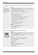
8.5 Cascade switching module (0-10 V interface for systems with Direct Digital Control
(DDC))
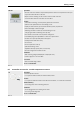
8.6 Accessories, weather-compensated controller - remote control
ICM Application
• Cascade module for switching two condensing boilers (MKB 240-3 A to MKB 560-3 A)
in conjunction with FW 200 or FW 500
• Communication with the condensing boilers and the controller via 2-wire BUS
• Function status LED for each boiler in the cascade
• Automatic load distribution to the connected condensing boilers
• Inputs
– NTC flow temperature sensor, for low loss header
– NTC outside temperature sensor
– External safety equipment, floating
– Heating circuit controller (ON/OFF contact), floating (24 V DC)
– Heating circuit controller (potential interface) 0 - 10 V
– 0-10 V interface, e.g. for DDC or third party controls
– Boiler communication (4 x via 2-wire BUS)
• Outputs 230 V AC, 50 Hz
– For further modules ICM: 230 V AC, 50 Hz, max. 10 A
– For pump: 230 V AC, 50 Hz, max. 2300 W
• Fault display: floating; max. 230 V, 1 A
Installation
• Wall mounting (height/width/depth: 165/235/52 mm)
• Power supply 230 V AC, 50 Hz, 10 A
Part no. 7 719 002 949
Tab. 30
FB 10 Application
• Remote control for adjusting the set value for the weather-compensated heating circuit
in conjunction with FW 100 or FW 200
• Can be used for heating circuit 1 or 2 (use the FB 100 for heating circuits 3 and 4)
• Communication with the controller via 2-wire BUS
Function
• 2-wire BUS technology, reverse polarity protected connection
• Set value adjustment for weather-compensated controller
• Room temperature display
• Fault code display
• No clock function
Installation
• Wall mounting (height/width/depth: 85/100/35 mm)
• Power supply 15 V via 2-wire BUS
Part no. 7 719 002 942
Tab. 31