Gebrauchsanleitung Mode d’emploi Gebruiksaanwijzing Operating instruction Kühlschrank Refrigerateur Koelkast Refrigerator ZQS 612 4A
Hinweise zur Benutzung der Gebrauchsanweisung Die folgenden Symbole erleichtern das Lesen der Gebrauchanweisung: D Sicherheitshinweise bezŸglich der Benutzung des GerŠtes RatschlŠge fŸr den korrekten Gebrauch und die optimale Ausnutzung des GerŠtes. Informationen zum Umweltschutz Sicherheitshinweise Bevor Sie Ihr neues KŠltegerŠt in Betrieb nehmen, lesen Sie bitte diese Gebrauchsanweisung aufmerksam durch. Diese sind Sicherheitshinweise.
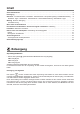
Inhalt Sicherheitshinweise . . . . . . . . . . . . . . . . . . . . . . . . . . . . . . . . . . . . . . . . . . . . . . . . . . . . . . . . . . . . . . . . . . . . . .2 Entsorgung . . . . . . . . . . . . . . . . . . . . . . . . . . . . . . . . . . . . . . . . . . . . . . . . . . . . . . . . . . . . . . . . . . . . . . . . . . . . .3 Gebrauch Vor Inbetriebnahme / KŸhlabteil - Inbetriebnhame / Temperaturregelung / KŸhlabteilausstattung . .
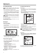
Gebrauch Vor Inbetriebnahme Man sollte mindestens 2 Std. warten, bevor das GerŠt in Betrieb genommen wird, damit das KŠltemittel zurŸckstršmen kann. ¥ Bevor Sie das GerŠt in Betrieb nehmen, beseitigen Sie den typischen ÇNeugeruchÈ am besten durch Auswaschen der Innenteile mit lauwarmem Wasser und einem neutralen Reinigungsmittel. SorgfŠltig nachtrocknen. KŸhlabteilausstattung Abstellregale ¥ Zur Einlagerung von Lebensmittel-Packungen verschiedener Grš§e, sind die AbstellflŠche hšhenverstellbar.
Tipps Energie-Einsparung ¥ Das GerŠt nicht in der NŠhe von Herden, Heizkšrpern oder anderen WŠrmequellen aufstellen. Bei hoher Umgebungstemperatur lŠuft der Kompressor hŠufiger und lŠnger. Bitte im Abschnitt ÒAufstellungÓ nachsehen. ¥ TŸr nur so lange wie nštig gešffnet lassen. ¥ Hšchste KŠlteeinstellung bei hoher Raumtemperatur und erheblicher Lebensmittelmenge kann fortdauernden KŸhlschrank-Betrieb verursachen, dabei kann sich eine Reif- oder Eisschicht an der hinteren Innenwand bilden.
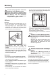
Wartung Vor jeder Reinigungsarbeit immer den Netzstecker aus der Steckdose ziehen. Dieses GerŠt erhŠlt im Kaltekreislauf Kohlenwasserstoff. Aus diesem Grund darf die Wartung und das NachfŸllen ausschlie§lich von autorisierten Fachpersonal durchgefŸhrt werden. ¥ TŸr offen lassen. Ein GefŠ§ auf den ersten Rost direkt unter das Ablaufloch stellen. Den Stšpsel wie in der Abbildung gezeigt entfernen.
1. Nehmen Sie die KŸchenmšbelsockelblende (1) ab; 2. demontieren Sie die BelŸftungsblende (2); 3. ziehen Sie vorsichtig die Verdunsterschale (3) heraus. Achten Sie darauf, da§ sich darin Abtauwasser befinden kann. 3 2 Innenbeleuchtung ¥ Vor dem Lampenwechsel GerŠt abschalten und den Netzstecker ziehen. 1. Lšsen Sie die Befestigungsschraube der Lampenabdeckung. 2. Heben Sie den beweglichen Teil ab, indem Sie wie in der Abbildung gezeigt darauf drŸcken. 3.
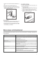
Kundendienst und Ersatzteile Sollten Sie nach o.e. PrŸfungen zu keinem Resultat kommen, so wenden Sie sich bitte an unseren nŠchsten Kundendienst. Um ein rasches Beheben des Schadens zu ermšglichen, ist es beim Anruf an den Kundendienst notwendig anzugeben: ¥ Modellbezeichnung ¥ Erzeugnis-Nummer (PNC) ¥ Fertigungs-Nummer (S-No.) Diese Angaben finden Sie auf dem Typschild rechts an der Innenseite des GerŠtes. Damit Sie die Daten schnell bei der Hand haben, empfehlen wir, sie hier einzutragen.
Elektrischer Anschluss Bevor Sie den Stecker in die Steckdose einstecken, ŸberprŸfen Sie bitte, dass die auf dem Typschild des GerŠtes angegebene Spannung sowie Frequenz mit dem Anschlusswert des Hauses Ÿbereinstimmen. Eine Abweichung von ±6% von der Nominalspannung ist zulŠssig. FŸr die Anpassung des GerŠtes an andere Spannungen muss ein Spartransformator angemessener Leistung vorgeschaltet werden. Wichtig Das GerŠt muss unbedingt vorschriftsmŠ§ig geerdet werden.
Einbau Nischenma§e 596 60 0 5 55 x ma + 5 min50 . - 600 3 DO013 Die Ma§e der Nische mŸssen den angegebenen Werten entsprechen. 1xB 2xC 1xA 1xK 18xI 2xG 2xL 2xF 2xD 1 1. Mitgelieferte Montageteile 2 Linke Seite Rechte Seite 2. Winkel rechts und links wie abgebildet befestigen. 10 + max. 890 mm 3. GerŠt in die Nische einschieben. Die zum Anschluss des GerŠtes nštige SchutzkontaktSteckdose sollte so positioniert sein, dass sich sie nicht vom GerŠt verdeckt wird.
1 B 4 4. Fugenabdeckprofil (B) am GerŠt ankleben, wie in der Abbildung gezeigt. 7 I a b C click 5 click 5. GerŠt festschrauben. c 8 6. MšbeltŸr montieren.
m 8m I F 27 ,5 cm 55 27 ,5 I F cm K cm G 10 13 1 2 45° A 3 11 14 7.
Montage der Sockelblende a = 100 b = 170 A = 820 B = 890 Achtung Um die FunktionalitŠt des GerŠtes nicht zu beeintrŠchtigen ist es notwendig das Original-LŸftungsgitter zu benutzen. ¥ Bei einer lichten Einbauhšhe Ma§ A=820 mm und einer Sockelblendenhšhe Ma§ a=100 mm kann die Sockelblende unverŠndert montiert werden. Ebenso bei einer lichten Einbauhšhe Ma§ B=890 mm und einer Sockelblendenhšhe Ma§ b=170 mm.
6 10 13 Achtung! Bei einer niedrigen Raumtemperatur (z.B. im Winter) kann es vorkommen, dass die Dichtung nicht perfekt am Schrank haftet. Die Wiederherstellung der Dichtung erfolgt automatisch nach gewisser Zeit. Wollen Sie aber diesen Prozess beschleunigen, so genŸgt es die Dichtung mit einem Fšn zu erwŠrmen. 9 6 12 11 3 Anschlagwechsel VerdampferfachtŸr 1 2 3 180° 4 5 FŸr Deutschland: Sie kšnnen Ersatzteile, Zubehšr und Pflegemittel on-line bestellen bei http://www.zanussi.
Comment lire votre notice dÕemploi Les symboles ci-dessous vous guideront au long de la lecture de votre notice: F Instructions liées à la sécurité lors de l’utilisation de l’appareil. Conseils pour une utilisation correcte de l’appareil afin d’obtenir les meilleures performances. Informations liées à la protection de l’environnement. Avertissements importants Ce sont des avertissements de sŽcuritŽ. Nous vous prions donc de les lire attentivement avant dÕinstaller et dÕutiliser votre appareil.
Sommaire Avertissements importants . . . . . . . . . . . . . . . . . . . . . . . . . . . . . . . . . . . . . . . . . . . . . . . . . . . . . . . . . . . . . . .16 Elimination . . . . . . . . . . . . . . . . . . . . . . . . . . . . . . . . . . . . . . . . . . . . . . . . . . . . . . . . . . . . . . . . . . . . . . . . . . . .17 Utilisation Avant la mise en service / Compartiment rŽfrigŽrateur - Mise en service . . . . . . . . . . . . . . . . . . .
Utilisation Avant la mise en service A cause du syst•me de transport, IÕhuile contenue dans le compresseur pourrait sÕŽcouler dans le circuit rŽfrigŽrant. Attendez 2 heures au moins avant de brancher lÕappareil pour permettre ˆ lÕhuile de refluer dans le compresseur. ¥ L'appareil Žtant convenablement installŽ, nous vous conseillons de le nettoyer soigneusement avec de l'eau ti•de savonneuse, pour enlever l'odeur caractŽristique de ÇneufÈ.
Conseils lÕon dŽsire arr•ter leur maturation. Ils devront alors •tre soigneusement enveloppŽs. ƒconomie dÕŽnergie Compartiment congŽlateur ¥ NÕinstallez pas lÕappareil ˆ proximitŽ de cuisini•res, radiateurs ou autres sources de chaleur. Si la tempŽrature ambiante est ŽlevŽe, le compresseur fonctionne plus frŽquemment et plus longtemps (voir chapitre ÒInstallationÓ). ¥ NÕouvrez pas la porte plus longtemps que nŽcessaire.
le moment ou le produit est achetŽ et le moment ou il est placŽ dans le compartiment congŽlateur. ¥ Ne placez ni bouteilles ni bo”tes de boissons gazeuses dans le congŽlateur, elles pourraient Žclater. ¥ Les aliments dégelés, même partiellement, ne peuvent être recongelés. Entretien DŽbranchez opŽration. lÕappareil avant toute Attention Cet appareil contient des hydrocarbures dans son circuit rŽfrigŽrant; lÕentretien et la recharge ne doivent donc •tre effectuŽs que par du personnel qualifiŽ.
Nettoyez pŽriodiquement l'intŽrieur de votre appareil avec de l'eau ti•de et du bicarbonate de soude. Rincez et sŽchez soigneusement. LÕappareil est ŽquipŽ dÕune grille dÕaŽration; elle doive toujours •tre nettoyŽe afin de garantir une bonne ventilation en partie arri•re et un fonctionnement optimal de lÕappareil. La structure de lÕappareil permet dÕeffectuer un nettoyage de la partie arri•re situŽe pr•s du mur en utilisant Žgalement un aspirateur. Pour effectuer cette opŽration, procŽdez comme suit: 1.
Consumer Services Une fois que tous ces contr™les ont ŽtŽ effectuŽs, si l'anomalie de fonctionnement persiste, adressezvous au consumer services le plus proche. Pour que l'intervention soit plus rapide, au moment de l'appel, il vaut mieux indiquer: ¥ le mod•le ¥ le numŽro de produit (PNC) ¥ le numŽro de sŽrie (S-No) Ces indications figurent sur le certificat de garantie ou sur la plaque signalŽtique situŽe ˆ l'intŽrieur de l'appareil, ˆ droite et en bas.
Branchement Žlectrique Contr™lez, avant de brancher l'appareil, si le voltage et la frŽquence indiquŽs sur la plaque signalŽtique correspondent ˆ ceux de votre rŽseau. TolŽrance admise: 6% en plus ou en moins. Pour l'adaptation de l'appareil ˆ des voltages diffŽrents, l'adjonction d'un autotransformateur d'une puissance adŽquate est indispensable. Important VŽrifiez si la prise de courant murale est en bon Žtat et apte ˆ recevoir la fiche du cordon d'alimentation du congŽlateur.
Encastrement Dimensions de la niche 596 60 0 5 55 x ma + 5 min50 . - 600 3 DO013 Les dimensions de la niche doivent correspondre ˆ celles indiquŽes dans la figure. 1xB 2xC + max. 890 mm 3. Mettre en place l’appareil. La prise murale doit se trouver impérativement hors de la niche d’encastrement de l’appareil. LÕappareil est ŽquipŽ de pieds rŽgables; pour rŽgler lÕappareil ˆ la hauteur souhaitŽe (890 mm max.), il est nŽcessaire dÕagir sur les 4 pieds rŽglables.
a I b C click click 5 5. Vissez lÕappareil. c 8 6. Montez la porte du meuble.
A 1 2 45° 3 11 14 7. Posez le couvre-joint (A).
Montage de la plinthe a = 100 b = 170 A = 820 B = 890 Attention! Pour ne pas compromettre le bon fonctionnement de lÕappareil, il est nŽcessaire dÕutiliser la grille dÕaŽration dÕorigine. ¥ Si la niche dÕencastrement de lÕappareil a une hauteur de A=820 mm et une hauteur de plinthe a=100 mm, la plinthe peut •tre montŽe sans modification. Il en est de m•me pour une hauteur dÕencastrement de B=890 mm et une hauteur de plinthe b=170 mm.
Attention! La rŽversibilitŽ de la porte une fois effectuŽe, contr™lez ensuite que le joint magnŽtique adh•re ˆ la carrosserie. Si la tempŽrature ˆ l'intŽrieur de la pi•ce est trop basse (en hiver, p.ex.), il se peut que le joint n'adh•re pas parfaitement. Dans ce cas, si on ne veut pas attendre que le joint reprenne ses dimensions naturelles apr•s un certain temps, on pourra accŽlŽrer ce processus en chauffant la partie intŽressŽe ˆ l'aide d'un s•che-cheveux.
Aanwijzing voor het gebruik van het instructieboekje N Met de waarschuwingsdriehoek en/of door signaalwoorden wordt de aandacht gevestigd op aanwijzingen die belangrijk zijn voor uw veiligheid of voor het juist functioneren van het apparaat. Na dit symbool wordt uitleg gegeven over de bediening en het praktisch gebruik van het apparaat. Tips en aanwijzingen voor een economisch en milieuvriendelijk gebruik van het apparaat.
schraap evenmin met metalen voorwerpen rijp of ijs af. Lekkage kan het gevolg zijn, hetgeen een onherstelbare schade aan het apparaat en bederf van de levensmiddelen veroorzaakt. ¥ Geen voorwerpen of methodes gebruiken om het ontdooiproces te versnellen die niet door de fabrikant zijn aangegeven. ¥ Nooit metalen voorwerpen gebruiken om het apparaat schoon te maken; dit zou het apparaat kunnen beschadigen.
Weggooien Informatie over de verpakking van het apparaat ¥ De materialen in dit apparaat die voorzien zijn van het symbool >PE<=polyethyleen >PS<=schuimpolystyrol >PP<=polypropyleen Alle gebruikte materialen zijn niet schadelijk voor het milieu! zijn geschikt voor recycling. Weggooien van oude apparaten Het symbool op het product of op de verpakking wijst erop dat dit product niet als huishoudafval mag worden behandeld.
Interieur Legvlakken ¥ De legvlakken zijn in hoogte verstelbaar. ¥ Daartoe het legvlak zover naar voren trekken tot het naar boven of onderen bewogen kan worden en eruit gehaald kan worden. ¥ Om de legvlakken op een andere hoogte te zetten in omgekeerde volgorde te werk gaan. D338 ¥ Om de ruimte beter te benutten, bij sommige modellen, kunt u de voorste platen over de achterste plaatsen.
stilstand, dient u de thermostaatknop op de koudste stand te draaien. Plaats vervolgens de diepvriesproducten na twee uur in de kast en draai de thermostaat terug naar de gebruikelijke stand. Interieur IJslaatjes Bij het apparaat worden 1 of meerdere ijslaatjes voor het maken van ijsblokjes geleverd. Vul ze met drinkwater en plaats ze in het vriesvak. Gebruik geen metalen voorwerpen om de laatjes los te wrikken. Tips Invriezen en bewaren ¥ Verdeel de levensmiddelen in handzame porties .
Vriesruimte ¥ In het vriesvak dient u de rijp te verwijderen, wanneer deze een laag van circa 5 mm vormt. Gebruik hiervoor de meegeleverde plastic spatel. Ga als volgt te werk: ¥ Omwikkel de levensmiddelen met meerdere kranten en bewaar ze op een koele plaats. ¥ Draai de thermostaatknop op ÇOÈ of trek de stekker uit het stopcontact. ¥ Laat de deur openstaan en plaats een bakje direct onder het afvoergaatje, haal de dop van de afvoer (zie afbeelding). 1. De sokkel (1) verwijderen. 3 2 1 S.I.013 2.
Storingen Indien de koelkast niet functioneert, controleer dan onderstaande punten, voordat u contact opneemt met onze service-afdeling: Storing Oplossing Temperatuur in het apparaat is te hoog Temperatuur is niet juist ingesteld. Zie hoofdstuk ÒInstellen van de temperatuurÓ. Plaats de levensmiddelen zo, dat de lucht vrij eromheen kan circuleren. Omgevingstemperatuur te hoog. Apparaat koelt te sterk. Temperatuur is niet juist ingesteld. Zie hoofdstuk ÒInstellen van de temperatuurÓ.
Installatie Bij het transport en het opstellen van het apparaat erop letten dat geen onderdelen van het koelvloeistofcircuit beschadigd worden. ¥ Tijdens normaal gebruik worden de condensor en de compressor die zich op de achterkant van het apparaat bevinden, warm. Om veiligheidsredenen moet de ventilatie zodanig zijn als aangegeven in de speciale afbeelding. Zie hoofdstuk ÒPlaats van opstellingÓ. ¥ Belangrijk: De netaansluiting mag alleen door gekwalificeerd personeel verwisseld worden.
Inbouw onder een werkblad Voorbereiding van het ventilatierooster Inbouw Nismaten Neem het rooster uit de onderste verpakkingsschaal. Deuropening links: - Het linker paneel (A) van het rooster vanaf de achterzijde afsnijden. 60 0 5 min50 . A 600 B DO013 De afmetingen van de nis moeten overeenkomen met de afmetingen uit de tekening. DO002/2 1xB Deuropening rechts: - Het rechter paneel (B) van het rooster vanaf de achterzijde afsnijden.
596 I 5 55 x ma + - 3 + max. 890 mm 5 3. Apparaat naar binnen schuiven. Het stopcontact met randaarde dat het apparaat voor aansluiting nodig heeft, moet zodanig ge•nstalleerd zijn dat het niet door het apparaat wordt bedekt. Het apparaat is voorzien van verstelbare voeten; u brengt het apparaat op de gewenste hoogte (max. 890 mm) door de voeten in de vier onderhoeken te verstellen. 5. Apparaat vastschroeven. 6. Meubeldeur monteren. 2 1 a 10 C 4 3 b 6 1 B 4 4.
a 1 b 2 45° C click 3 click c 8 Boven Möbeltür Innenseite 11 a I = = 1 c = 2 10 b 9 = 12 I F m 8m 27 ,5 c 55 27 ,5 F cm 10 K G 13 40 I m cm
Montage van het sokkelpaneel Belangrijk Het originele ventilatie-rooster dient gebruikt te worden opdat de functionaliteit van het apparaat niet belemmerd wordt. ¥ Bij een binnenwerkse inbouwhoogte maat A=820 mm en een sokkelpaneelhoogte maat a=100 mm kan het sokkelpaneel ongewijzigd worden gemonteerd. Dat is ook zo bij een binnenwerkse inbouwhoogte maat B=890 mm en een sokkelpaneelhoogte maat b=170 mm.
Wijzigen van de deurdraairichting Voor het wijzigen van de deurdraairichting als volgt te werk gaan: 6 6 4 1 7 8 5 6 2 3 1 2 6 10 13 9 6 11 3 42 12 Attentie! Bij een lage omgevingstemperatuur (bijv. in de winter) kan het voorkomen dat de deurafdichting niet perfect aan de kast hecht. De afdichting wordt na een bepaalde tijd vanzelf in vorm getrokken. Als u dit proces wilt bespoedigen, is het voldoende om de afdichting m.b.v. een haardroger te verwarmen.
Omkeren draairichting deurtje 1 2 3 180° 4 5 43
50 44 45 46 47 48 49 51 52 53 54 55
Instructions for the use of the instructions booklet t Notes which are important for your safety or for the proper functioning of the appliance Supplementary information regarding operation and practical applications of the appliance. Tips and notes concerning economical and environmentally sound use of the appliance Safety Instructions This information has been provided in the interests of your safety. Please read it before installing or using the appliance.
Disposal of old appliances The symbol on the product or on its packaging indicates that this product may not be treated as household waste. Instead it shall be handed over to the applicable collection point for the recycling of electrical and electronic equipment. By ensuring this product is disposed of correctly, you will help prevent potential negative consequences for the environment and human health, which could otherwise be caused by inappropriate waste handling of this product.
Temperature Control Door shelves ¥ The following effects are of significance in respect of the interior temperature: ¥ Ambient temperature ¥ Quantity and temperature of the food stored; ¥ Frequency with which the door is opened and how long it is left open ¥ the location of the appliance. ¥ The temperature inside the appliance is automatically adjusted. ¥ Setting ã1Ò = hightest temperature, warmest setting ¥ Setting ã6Ò = lowest temperature, coldest setting.
¥ Cooked food, cold cuts, jelly, etc.: these should be well covered and can be stored on any of the glass shelves. ¥ Fruit & vegetables: these should be thoroughly cleaned and placed in the bottom bin/s. ¥ Butter & cheese: these should be placed in special airtight containers or wrapped in aluminium foil or polythene bags to keep out as much air as possible. ¥ Milk bottles: these should have a top and should be stored in the bottle rack on the door.
Maintenance Unplug the appliance before carrying out any maintenance operation. Warning This appliance contains hydrocarbons in its cooling unit maintenance and recharging must therefore only be carried out by authorised technicians. ¥ Leave the door open, place a basin on the top shelf of the refrigerator compartment, under the drain hole, remove the plug as shown in the figure. Defrosting Refrigerator compartment ¥ Defrosting the refrigerator compartment is automatic.
The structure of the appliance permits cleaning of the rear zone close to the wall, using a vacuum cleaner. 1. Remove the plinth (1), then the ventilation grid (2); 3 2 Changing the light bulb ¥ Should the interior light fail to work, first switch off the appliance and disconnect from the electricity supply, then replace the bulb as follows: 1. unscrew the light cover securing screws. 2. unhook the moving part by pressing it as shown in the figure. 1 S.I.013 2.
Customer service and spare parts If you cannot find the remedy for a malfunction in these operating instructions, please contact your dealer or our customer service department and consult the Guarantee card. Selective ordering of replacement parts can save unnecessary travel and costs. For this reason always provide the following appliance information: ¥ Model Name ¥ Model Number (PNC) This information can be found on the rating plate inside the cabenit on the left hand wall.
Electrical connection Before plugging in, ensure that the voltage and frequency shown on the serial number plate correspond to your domestic power supply. Voltage can vary by ±6% of the rated voltage. For operation with different voltages, a suitably sized auto-transformer must be used. Important The appliance must be earthed. The power supply cable plug is provided with a contact for this purpose. If the domestic power supply socket is not earthed.
Building-in Dimensions of the recess 596 60 0 5 55 x ma 5 min50 . + - 600 - 3 + max. 890 mm DO013 The dimensions of the recessed installation area must correspond with those indicated in the figure. 1xB 2xC 3. Push the appliance into place. The plug socket necessary for connection of the appliance to the electricity supply should be positioned, so that the plug is not placed in the recess. To adjust the height proceed as follows: - Loosen or tighten the two front feet.
a I b C click click 5 5. Screw appliance into place and retain the cabinet with screws (I) through the securing brackets into the worktop or adjacent woodwork as necessary. c 8 6.
A 1 2 45° 3 11 14 7. Refit the covering strip (A).
Fitting the plinth ¥ For an opening height dimension A=820 mm and a plinth height dimension a=100 mm, the plinth may be fitted without adjustments. The same applies to an opening height dimension B=890 mm and a plinth height dimension b=170 mm. ¥ For plinth heights greater than a=100 mm, b=170 mm, a cut should be made in the plinth, 580 mm wide, in the centre of the appliance position, leaving a remaining height of a=100 mm, b=170 mm. ¥ Attach plinth to the kitchen units.
Inner door reversal 1 2 3 180° 4 5 56 58 57
www.electrolux.