
Installation Guide

1300 S. Wolf Road • Des Plaines, IL 60018 • Phone 800-323-5068 • Visit us at www.acuitybrands.com/juno-undercabinet
©2017 Acuity Brands Lighting, Inc. Rev 3/17 P3153
1 of 2
JUNO SOLO-TASK LED UNDERCABINET/DISPLAY LIGHTING
USTL1 and USTLR1 Fixtures
SAVE THESE INSTRUCTIONS
WARNING: For your safety, read and understand instructions completely before starting installation.
Before wiring to power supply or secondary devices, turn off electricity at the fuse or circuit breaker box.
Note: Juno recessed fixtures are designed to meet the latest NEC requirements and are listed in full compliance with
UL 2108. Before attempting installation of any recessed lighting fixture, check your local electrical building code.
This code sets the wiring standards and installation requirements for your locality and should be understood before
starting work.
INSTALLATION INSTRUCTIONS
Installation Instructions
Step 1. Juno Solo-Task LED Undercabinet fixtures are intended for use with any 12V
AC Class 2 transformer. Note: A single fixture consumes approximately 5W per fixture
depending on transformer and system loading. For best performance, it is recom-
mended that fixtures are operated with Juno TL602E or TL548U electronic transform-
ers, or the TL576 magnetic transformer. Refer to the transformer specifications for
minimum and maximum loading. Make certain power delivered to fixtures does not
exceed 12V AC. Follow all local & national electrical codes for wiring from the trans-
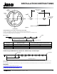
former to the fixtures, or from fixture to fixture if
daisy-chaining (Refer to wiring diagram).
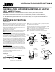
Step 2. Remove cover from the base assembly by twisting 1/4 turn counter-clockwise.
Step 3. Solo-Task luminaires can be surface mounted or recessed mounted.
Surface Mount Installation
Use the template (Fig. 3) to drill two pilot holes for the wood screws before attaching
the fixture to mounting surface (Fig. 1.) For a typical under-kitchen cabinet installation,
it is recommended to space fixtures 9” to 9-1/2” from back wall to fixture center for
even illumination of counter and backsplash. Wiring from transformer to fixture, and
fixture to fixture can be handled two ways. Option-1: wiring exposed on the underside
of the cabinet (Fig 1a). When using option-1 with exposed wiring, it may be easier to
wire fixtures before they are installed to mounting surface. Mark the center points of
fixtures on mounting surface and drill mounting pilot holes
(Fig 3). Take your fixture center-to-center measurement. By subtracting 2” from this
dimension, you will have the wire length required to connect fixtures together (refer
to wiring diagram). Option-2: bring wires in from above fixture mounting surface
(Fig 2a). When using option-2 use the template (Fig 3) to drill two holes for wiring to
pass through mounting surface (Fig 2a). For optimal, even illumination, it is recom-
mended to space fixtures 18” apart. However, fixture spacing less than or more than
18” will still provide high-quality lighting performance.
Recessed Mount Installation
All USTLR1 fixtures are pre-configured for recessed mounting. However, USTL1
fixtures require a Recessed Conversion Kit (USTREC) for recessed mounting.
Replace cover on existing USTL1 fixture with new cover from Recessed Conversion
Kit. Secure the two push-in springs with the two screws provided (Fig. 1b). Locate
mounting position and cut a 2-3/4” hole (Fig. 2b). It is recommended to space fixtures
9”-9-1/2” from back wall to fixture center with fixtures spaced 18” apart.
Caution – To reduce the risk of fire, do not install in a compartment smaller than 12
inches by 12 inches by 12 inches.
Step 4. Route Class 2 wiring from the secondary side of the transformer to fixture(s).
Class 2 (CL2) cable or equivalent code compliant wiring is required. Strip secondary
leads 3/16” for insertion into fixture terminals.
Step 5. Secondary wiring is not polarized. After inserting leads into terminal, tighten
terminal block set screws securely to retain wires to 4 in-lb minimum (Fig. 1a.) Make
certain no bare conductors are exposed after attachment to terminals.
Step 6. Use enclosed adhesive backed wire management clips provided with Juno
packaged wire (UST18G) and Solo-Task 3-fixture kit (UK3STL).
Step 7. Complete installation of all fixtures before restoring electrical power.
Wiring Diagram
CLASS 2 12V AC OUTPUT
PLUG IN TRANSFORMER
LED SOLO-TASK
FIXTURE
LED SOLO-TASK
FIXTURE
CENTER-TO-CENTER
FIXTURE SPACING
WIRE LENGTHS EQUALS CENTER-TO-CENTER FIXTURE
SPACING MINUS 2”. STRIP EACH END 3/16”.
Figure 1a Figure 1b
Figure 2a Figure 2b
COVER
USTLR1
SOLO-TASK
CUT WITH
2-3/4" HOLE
SAW
TERMINAL
BLOCK
SET SCREW
HOLES FOR
ATTACHMENT
WOOD SCREWS
HOLES FOR
PASSING
WIRES
THROUGH
CABINET
CABLE WIRE
WOOD
MOUNTING
SCREW
COVER
SCREWS
FOR PUSH-IN
SPRINGS
PUSH-IN
SPRINGS
CABLE WIRE
TERMINAL
BLOCK SET
SCREW