
Installation Guide


JUNO 2" LED RECESSED HOUSINGS
INSTALLATION INSTRUCTIONS
WARRANTY
Juno Lighting Group provides five year limited warranty on LED components from date of purchase. Juno Lighting Group’s obligation is expressly
limited to repair or replacement, without charge, at Juno Lighting Group’s factory after prior written return authorization has been granted.
This warranty shall not apply to products which have been altered or repaired outside of Juno Lighting Group’s factory. This warranty is in lieu of all
other warranties, expressed or implied, and without limiting the generality of the foregoing phrase, excludes any implied warranty of merchantability.
Also, there are no warranties which extend beyond the description of the product on the company’s literature setting forth terms of sale.
Product Services Phone (888) 387-2212
1300 South Wolf Road • Des Plaines, IL 60018 • Phone 800-323-5068 •
Visit us at www.junolightinggroup.com
© 2014 Juno Lighting, LLC. Printed in U.S.A. Rev 5/14 P3697 pg 2 of 2
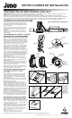
ELECTRICAL CONNECTION INSTRUCTIONS
Step 1. Provide electrical service according to national and/
or local electrical code to the junction box located on the
mounting frame. Supply wire insulation must be rated for at
least 90°C. Note: This fixture requires a flexible
electrical supply.
Step 2. Remove wiring compartment cover. Remove the
appropriate knock-out(s) to accommodate the type of
electrical supply being used (Fig. 13):
Flexible Metal Conduit or Non-Metallic Sheathed Cable.
Remove appropriate round knock-out(s) and connect conduit
to junction box with proper connectors (not supplied).
Step 3. Strip supply wire 3/8” and insert each supply wire into
appropriate connector. Connect black fixture wire to hot, white
fixture wire to neutral and green fixture wire to ground.
(Fig. 13).
Connect violet (+) and gray (-) dimmer wires, ( -U models only).
Step 4. Place all wiring and connectors back in wiring
compartment and replace cover, taking care not to pinch
any wires.
Figure 13
DRIVER REPLACEMENT
Driver replacement by qualified electrician only.
Fixture must be removed to access driver.
Step 1. Pull LED module back down thru the ceiling opening.
Step 2. Loosen 2 screws on top of LED trim module and
remove cover. Unplug connector.
Step 3. Loosen ceiling clamp screws. Push ceiling clamps up
into the ceiling cavity. Pull complete frame assembly back thru
the ceiling opening.
Step 4. Open wiring compartment and remove connectors
from driver. Remove 2 fasteners from driver to pull it free from
the wiring compartment.
Step 5. Insert and secure new driver into wiring compartment.
Make wiring connections and re-install fixture as described in
the appropriate section of these instructions.
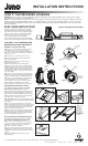
OPTIC REPLACEMENT – DOWNLIGHTS
Step 1. Pull baffle or reflector out of trim. It may be necessary
to insert a small screwdriver between the baffle and the optic
holder to pry it free (Fig. 14).
Step 2. Twist black optic holder counter-clockwise to remove
optic and holder (Fig. 15).
Step 3. Remove optic from black optic holder. Snap the new
optic into the black optic holder (Fig. 16).
Step 4. Align the tabs in the heatsink to the slots in the optic
holder and push optic into fixture. Twist optic holder clockwise
to secure (Fig. 17).
Step 5. Press the baffle or reflector back into the fixture.
Note that the baffle has depressions in it that must align with
the tabs on the trim ring (Fig. 18).
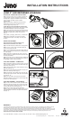
OPTIC REPLACEMENT – ADJUSTABLES
Step 1. Insert a small screwdriver into the slots between the
gimbal face and body. Pry off the face. It may be necessary
to pry in a few locations to pull the face evenly off. Optic will
come free after the face is pulled off (Fig. 19).
Step 2. Place the desired optic onto the gimbal face.
Align the 2 posts on the gimbal face with the spring receivers
in the gimbal body. Push the face and optic into the gimbal
body (Fig. 20).
Figure 14 Figure 15
Figure 16 Figure 17
Figure 20Figure 19
Figure 18